A very warm welcome to my most ambitious project to date. In this project I’m going to attempt to design and build a sprite-based graphics accelerator that will function as a co-processor to an MCU. Using cheap off-the-shelf components I’m hoping to achieve a level of gaming performance that compares well to popular commercial hand-held gaming consoles.
I’m hoping that I’ll learn a few new tricks along the way, and, if the ideas currently zinging around inside my head all land the right way up and in the right order then I should be able to write a demo or two, maybe even a small game as a proof of concept. Naturally this project will be entirely open source so if you feel the need to copy, extend or just kick some tires then you’ll be doing so with my blessing.
Interested? I hope you are. So sit back and grab a beverage because this may take some time.
System design
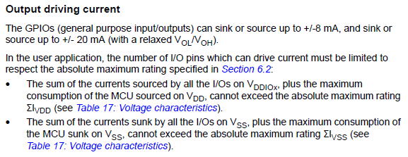
I decided up-front that this would be a sprite-based 2D graphics accelerator. Sprites are graphical objects that the developer can place at arbitrary locations on the screen. They can overlap each other in a predictable Z-order and can have areas of transparency so that they may be non-rectangular.
A frame from a game is assembled from a collection of sprites, some of which will represent the player’s environment, some will represent the player and other game actors and still others will represent transients such as explosions and other effects.
Sprites are the only graphics on the display and each frame is assembled independently by placing each sprite at its configured position in the z-order. This means that additional hardware such as bit-blitters are not required and moving a large sprite around costs the same as moving a small sprite. Radical changes between frames are as cheap as no changes at all.
All the cellphone LCDs that I’ve seen have a default refresh rate of approximately 60 frames per second (fps) so I decided on a target of 30 fps for the main engine. This means that I can spend 1/60s preparing the next frame in a frame buffer and then the next 1/60s sending it to the LCD.

This technique is known as double buffering and, together with careful timing of the refreshing of the display data is the primary method by which we avoid tearing.
The LCD retrieves data from its internal memory from top to bottom, left to right. If we happen to be updating an area of the screen at the same time as the LCD is retrieving data from it to push to the panel then we’ll see an ugly effect called tearing where the image on the display consists partly of the previous and next frames.
This effect can be seen in some PC games where an option is provided to ‘disable vsync’ allowing players to achieve a higher display refresh rate at the expense of image consistency.

Luckily the LCD provides a signal that they often call ‘Tearing Effect’ (TE). TE goes active during a part of the display known as the ‘vertical blanking period’ which is a few lines at the top and bottom of the panel that you can’t see.
To achieve a flicker-free display we need to start refreshing data when TE goes active and we must move at least as fast as the display refresh so that it doesn’t catch us up before all the data has been uploaded.
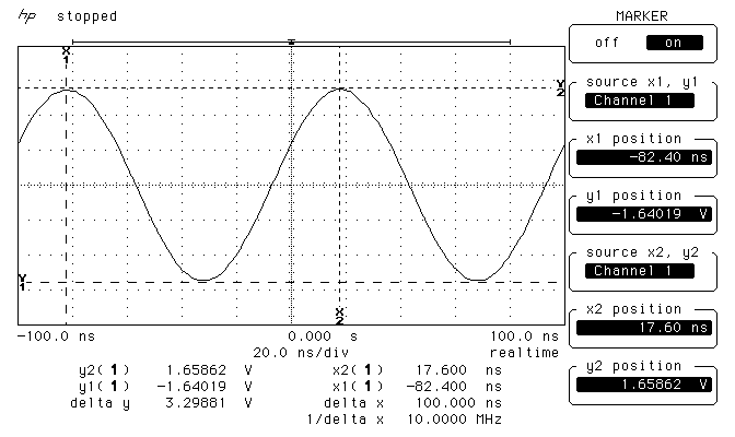
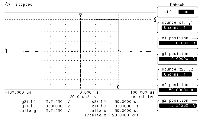
The timing here is a critical part of the design. The LCD controller must offer a write speed that allows a complete frame to be written in less time than the display refresh rate and our graphics accelerator must be able to write data out at that speed.

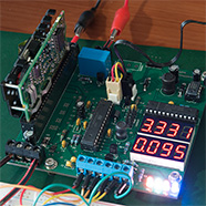
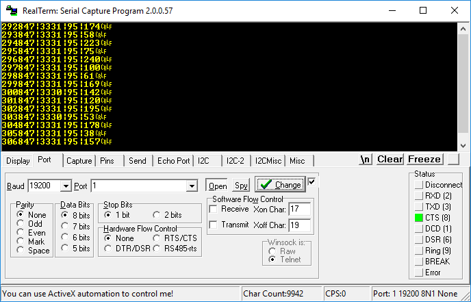
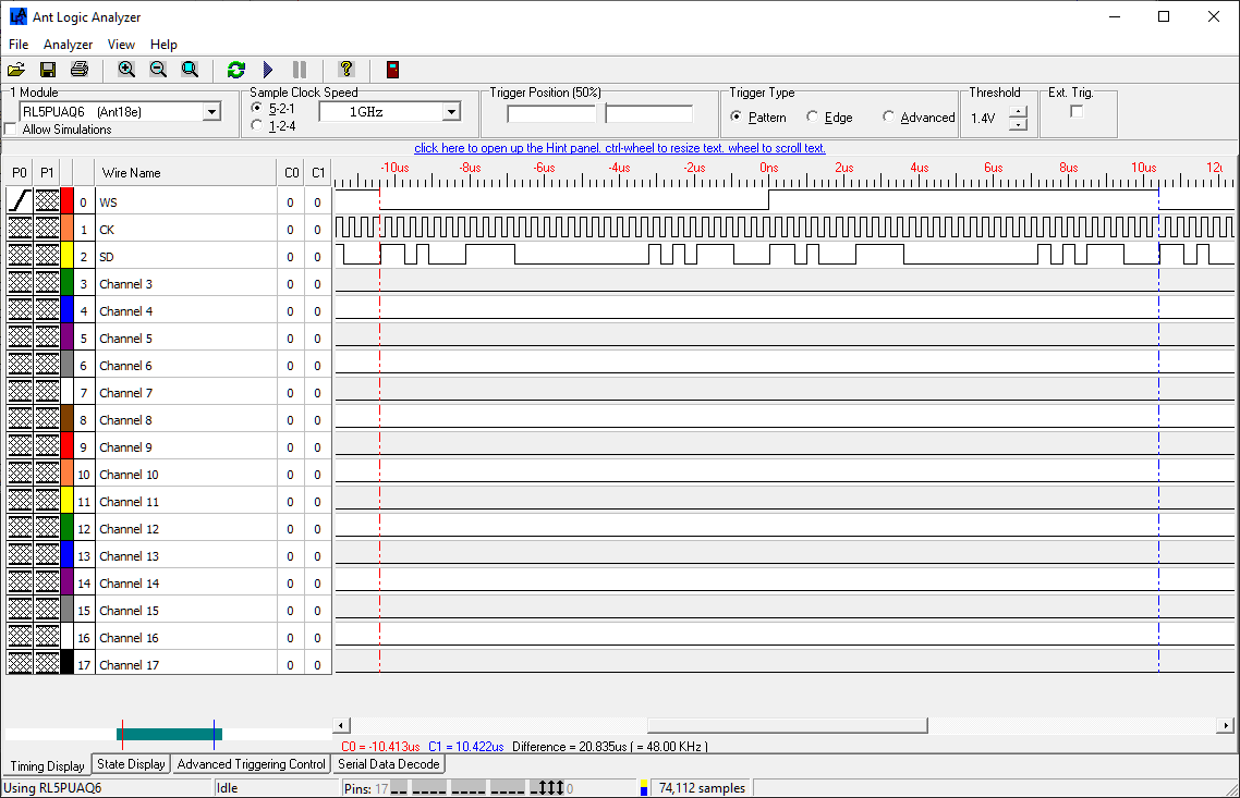
Click for larger
The screenshot shows the TE signal from the LCD used in this project captured using my Ant18e logic analyser.
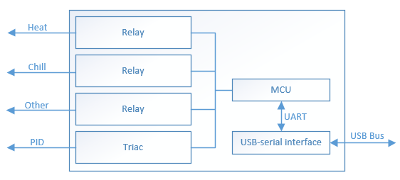
High level components
It’s not possible to do all of this using an unassisted MCU with CPU power alone. We need to offload the heavy lifting involved with moving all those graphics around to a co-processor and as you can tell from the title of this article I’ve elected to use an FPGA to do that. Why an FPGA? The core of this graphics accelerator involves interacting with external components at high frequencies and with nanosecond-level timing margins. The amount of combinatorial logic involved is fairly low and so an FPGA is the obvious choice.
The FPGA will not be the only processor on this board. Games need a controller, and it needs to be a pretty decent one if we want to be able to perform game-engine computations in the fixed period available to us between frames. I’ve elected to include the MCU on-board instead of just breaking out the FPGA interface to a pin header because parallel buses and high signal frequencies will not play well with flying interconnect wires.
Games need graphics, lots of graphics. To deal with that I’m going to provide an SD card slot that the controller can use to access graphics and other data authored on a computer. The FPGA isn’t going to be talking to the SD card because SDIO does not offer a predictable, constant sustained transfer rate so I’ll provide a high-capacity flash memory IC that the FPGA can use to read the graphics at high speed.
The FPGA needs a RAM buffer to render its frames to. FPGAs do come with some different types of very fast RAM on board but it’s nowhere near large enough for a frame buffer so we’ll need to add a chunk of our own. Asynchronous Static RAM (SRAM) offers the simplest interface and the possibility of high sequential throughput so we’ll use it in preference to SDRAM. The other option, SDRAM, is cheaper and offers densities far in excess of what we need but the controller is much more complex and does not deliver a benefit in this design.
Of course we also need an LCD to display the actual image and I’m going to choose the highest resolution device that I can possibly get away with given the space and time constraints imposed by the other resources.
As a final touch I’ll throw in an EEPROM to allow a relatively small amount of data to be persisted while the power’s off. High score tables are an example of such data.
Now let’s look at a block diagram that illustrates what I’ve just talked myself into.

Component selection
Now that the basic system design has been decided, it’s time to choose the actual components that will be used on this board.
The LCD

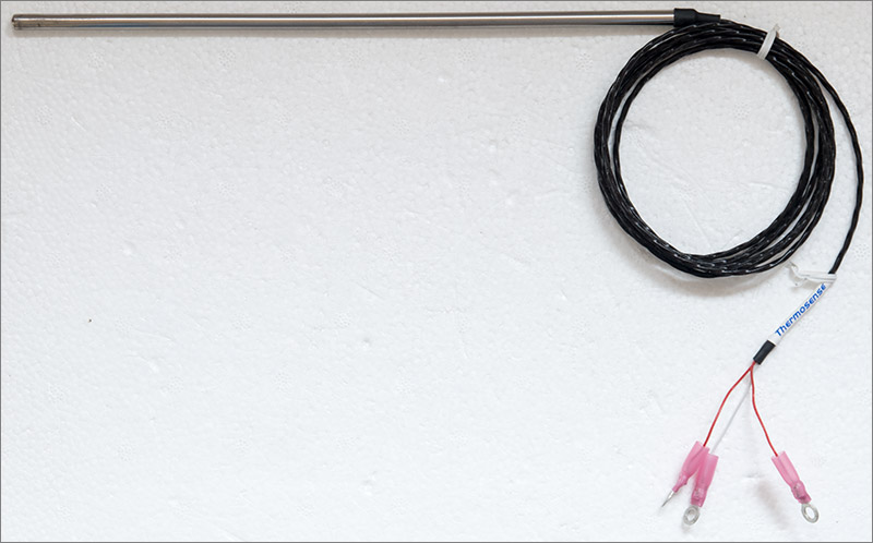
The 3.2″ Sony Vivaz LCD
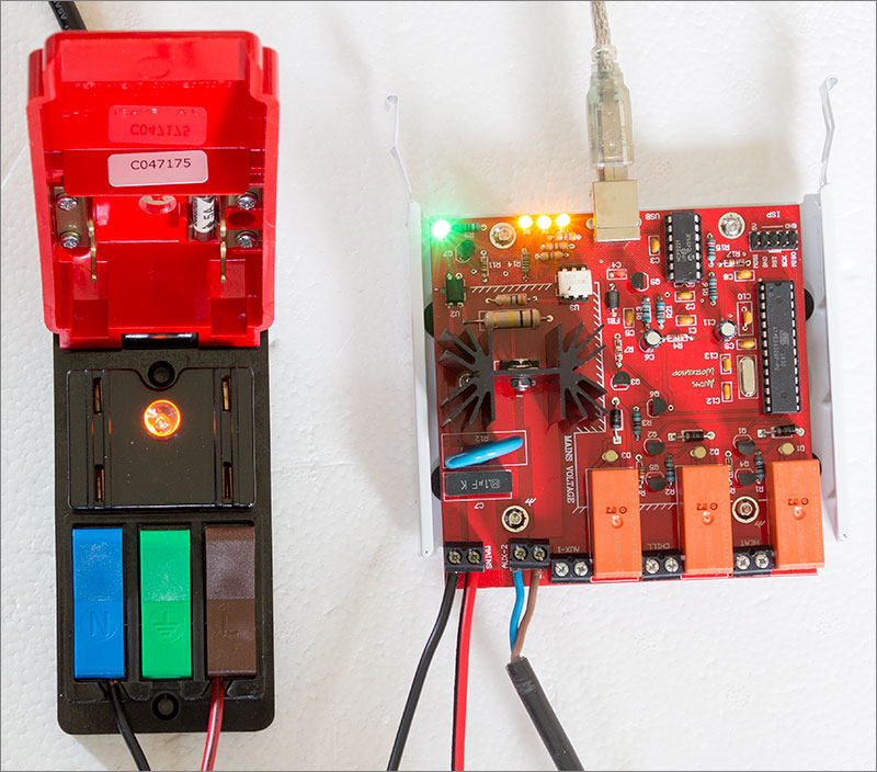
Just like in my previous project, the halogen reflow oven, I’ve selected the 640×360 LCD from the Sony Vivaz U5 cellphone. You can read all about my initial reverse engineering effort for this display in this article.
This display ticks all the important boxes for this project. Good quality replacement parts are cheaply available on ebay, I’ve worked with it before and I know it’s reliable, and the timings and resolution fit perfectly.
I’ll be driving the display in 16-bit 5-6-5 RGB mode which means I need 2 bytes per pixel. That means the frame buffer is going to have to be at least a 4 megabit SRAM part. If the resolution were any higher then it would push me into an expensive 8 megabit part and in all likelihood the timing would be too tight to achieve in the selected FPGA, again pushing up the cost and complexity into undesirable territory.
The latch

This is a small part with a critical task. If I’m going to squeeze my design into the limit of 63 FPGA user IOs then I need to take steps to reduce the pin count wherever I can. The 8-bit latch will be used to reduce the pins required by the LCD data bus from 16 to 9 (1 extra pin is required for the ALE signal).
The performance of the latch is critical to the success of the design. My timing constraints are such that the ALE line will be high for only 10ns give or take some skew so I needed to select a part that met the criteria. The Texas Instruments SN74ABT573APW device fits the bill perfectly, requiring only a 3.3ns high pulse. Not only is it fast enough but it has a sensible pinout where the outputs are on opposite sides of the device to the inputs which is perfect for a bus. Quite a lot of multi-bit latches have a crazy pinout where outputs are adjacent to the inputs which guarantees you a mess of vias as you try to reassemble your bus lines on the PCB.
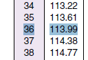
The FPGA

I chose the Xilinx Spartan 3 XC3S50 in the -5 high speed grade as the FPGA that I would use. This is the smallest, cheapest and most hobbyist-friendly Xilinx FPGA in production and it’s still got 100 pins, somewhat validating the FPGA’s reputation as being big, formidable devices to work with. At least it’s not a BGA is all I can say.
The top two manufacturers in the FPGA market are Xilinx and Altera. Xilinx was first off the block in the FPGA industry and has the lion’s share of the market. My choice of Xilinx over Altera is based on local availability of the parts. Farnell UK is a Xilinx supplier and so it made sense for me to choose Xilinx. Both manufacturers offer free synthesis and simulation software and a similar product line-up so if Altera parts are easier to find in your locality then I’m sure you’ll get by just fine with Altera FPGAs.
Back to the XC3S50. It’s quoted as having 50,000 logic gates but that’s an aggregate number that isn’t really reflected in the resource usage you see when you synthesise your design. The key figures are that it has 1,536 slice flip-flops, 768 slices and 1,536 4-input LUTs.
As well as the core logic gates there are some additional on-chip resources that are going to be crucial to my design. There are 73,728 bits of dual port block RAM (BRAM), 12,228 bits of distributed RAM, 4 hardware multipliers and 2 digital clock managers (DCM).
It’s important to note that the distributed RAM is not an independent resource like the block RAM. Distributed RAM is implemented using LUTs, reducing the area available to hold your design logic.
I will use the BRAM to hold the sprite records, the distributed ram to implement a FIFO for incoming commands from the MCU and a DCM to synthesize a high frequency clock from an external oscillator.
Of those 100 pins, 63 are available for user IO. That might seem like a lot but once you start adding up the SRAM address and data buses, the MCU interface and the LCD bus it doesn’t look so generous after all. You’ll see how I squeeze it all in as you read the rest of this article.
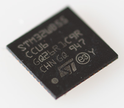
Finally, do you see that huge bump up the top right of the package that looks like it ought to be the pin 1 indicator? Well it’s not. Pin 1 is down at the bottom left next to the much smaller bump. I found that one out the hard way. The convention with ICs is that if you hold them with the printed text upright then pin 1 will be at the bottom left.
The oscillator

If you want to do anything significant in an FPGA then you need to supply it with a clock signal from an oscillator. A cheap quartz crystal isn’t sufficient, it must be a full oscillator. These cost slightly more but are still very affordable.
The oscillator I chose is the 40MHz Fox FXO-HC73 and it will be fed to one of the global clock pins on the FPGA. FPGAs provide dedicated low-skew routing resources for clock signals to ensure that all the parts of your design that run off the clock are closely synchronised.
The entire FPGA design runs at 100MHz so I use one of the DCM resources inside the FPGA to multiply up the 40MHz signal to 100MHz. There’s no critical reason to choose 40MHz for the oscillator, it’s just one of the cheaply available frequencies that multiplies/divides to 100MHz easily and isn’t too fast to cause routing problems on the PCB.
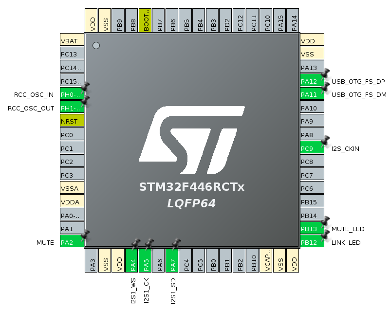
The MCU

The MCU is going to be the STM32F429VIT6. It’s a 180MHz 32-bit ARM Cortex M4 MCU from ST Microelectronics that comes with 2Mb of flash memory, 256Kb of SRAM and a hardware FPU capable of single-cycle add and multiply operations on single-precision floating point numbers.
It’s a formidable MCU and I chose it because of its high core clock speed and abundant resources. All the game logic has to execute in a fixed time period so it pays to have a high clock speed. It’s almost certainly overkill, and the fact that the F429 contains a ‘Chrome-ART’ accelerator that has considerable functional overlap with the sprite accelerator has not gone un-noticed. However I decided to err on the safe side and fit the fastest STM32 currently available.
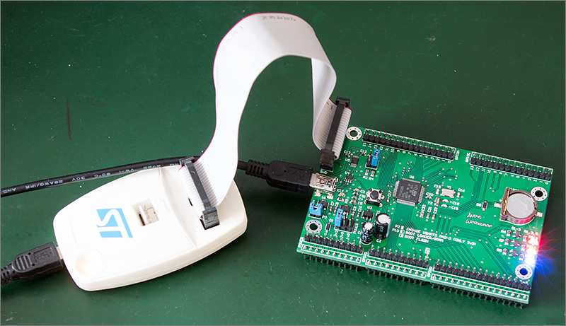
Programming the device is easy, all I need to do is expose the SWD pins, connect up my ST-Link/v2 programmer and I can program it using OpenOCD.
The MCU is available in a number of packages with the LQFP-100 being the one with the fewest number of pins. Not exactly small but there’s already a quad 100 pin package on this board so what’s another one between friends?
The flash

The flash device is a 128 megabit (16 megabyte) S25FL127S SPI part from Spansion. This device was selected for its low cost, high speed and high capacity. Uncompressed graphics require lots of space and multi-frame sprites only multiply up that space requirement. This device has the capacity for 8 megapixels, or 36 complete full frames of data.
If you think SPI flash is not going to be fast enough then you’re going to be pleasantly surprised. The Spansion device can operate in a non-standard 4-bit output mode and can be clocked as high as 108MHz giving a maximum data output rate of 54 megabytes per second. Operating this kind of bus is bread and butter to an FPGA. I’ll clock the flash device at the full internal FPGA clock speed of 100MHz and I’ll use the 4-bit quad output mode to enable me to read out a 16-bit pixel in 4×10 = 40ns. This just happens to be exactly how long I need to write out a pixel to the SRAM frame buffer. Serendipitous indeed.
The SRAM

The SRAM IC that I chose is the ISSI IS61LV5128AL 4Mb device arranged in a 512Kb x 8-bit layout with an access time of 10ns (100MHz). The LCD pixels are 16-bits wide so I’ll need to do two SRAM accesses to read or write a full pixel but I’ll save 8 pins from my FPGA budget.
4 megabits is enough to hold 262,144 pixels. My LCD has 640×360 = 230,400 pixels so there’s 31,744 to spare. I don’t have a use case for those extra bits so they’re just going to be left unused in this design.
The 10ns access time means that I’ll have no trouble doing a full pixel write in the same time frame that a 16-bit pixel is read out from the flash IC. Conversely, I’ll be able to read out a full pixel in the same time period that it takes to write out a pixel to the LCD. FPGAs are designed to do multiple tasks concurrently with nanosecond precision so everything should line up nicely.
The EEPROM

The EEPROM plays a peripheral, non-core role in the design. It’s just there so that we’ve got some space to store arbitrary data that must survive a power-cycle. Unlike the popular Atmel AVR chips used in the Arduino, the STM32 MCUs do not come with EEPROM built-in. It’s possible to write flash-pages inside the STM32 on-demand so EEPROM can be emulated but with the cost of I2C EEPROMs so low I figured I might as well include one here.
The device I chose is a 32Kbit BR24G32FJ device from Rohm in the SOIC-8 package.
EEPROMs are a rare example where there is cross-manufacturer pinout and operational compatibility. You can pretty much choose any device in the right-sized package and it’ll work over the I2C protocol just the same as a device from a different manufacturer. If you’re building this project yourself then feel free to substitute an alternative part if the Rohm device is not available where you live.
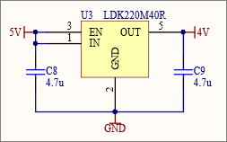
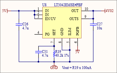
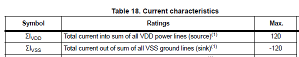
The power supplies

There are no fewer than five different levels on this board, six if you count the output from the LCD backlight boost converter. A 5V external power supply feeds the LDO regulators that supply power to the rest of the system. Nearly all the components are powered off an AMS1117 3.3V regulator except, predictably, the FPGA. It requires 2.5V and 1.2V for its auxiliary and internal operations in addition to the 3.3V level that we use for all the IOs. The last level is the 2.8V required for the LCD panel supply.
When running in sprite mode with the LCD backlight at 90% the system will draw nearly 400mA down the 5V line. For this reason I chose 3.3V, 2.5V and 1.2V regulators that have a big margin in the amount of current that they can supply. I didn’t want to be left with an iffy power supply at the end of the day. The 2.5V and 1.2V regulators are both from the Taiwan Semiconductor TS1117 family and the 2.8V regulator is the ZXCL280H5TA by Diodes Inc.
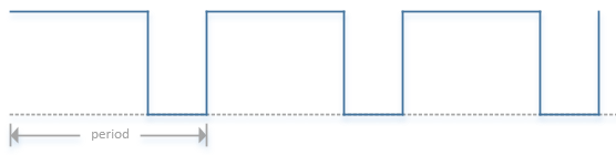
It’s all about the timing
All of the selected components must work together within the timing constraints imposed by how fast we can get data out of the flash IC, into the SRAM frame buffer and subsequently to drive into the LCD. Here’s a diagram that shows a high level overview of the timing from the point of view of the game developer.

At the start of the first frame the FPGA will drive a busy signal high to indicate that it’s about to start parsing the sprite configuration stored in the internal BRAM. It will use this configuration to fetch graphics from the external flash and write them out to the SRAM frame buffer. During this period it is not safe to write any commands to the FPGA that would cause the sprite state to change.
When the FPGA has finished this task it will drive the busy signal low again. This transition must happen before the start of the next frame or display corruption will be observed. The MCU should use this period to run its game logic and prepare for writing out the new state of the display.
During the second frame the FPGA takes the data in the frame buffer and writes it out to the LCD as a complete frame. During this period it is safe for the MCU to upload the new state of the world to the FPGA. In fact it’s safe to do so as soon as the busy signal goes low.
When frame two is complete the whole cycle starts back again at frame one. Since the display is running at 60fps what we’ve got here is a 30fps sprite engine.
More about the sprites
I’m planning to provide two operating modes for the FPGA. In passthrough mode the FPGA will send data that it receives from the MCU directly through to the LCD bus. This allows the MCU to directly drive the embedded Renesas R61523 controller in the LCD at a decent speed but not as fast as if it were directly connected. This mode is used to initialise the LCD controller, display introduction and high score screens and to send the command sequence that prepares it for entering sprite mode.
In sprite mode the FPGA takes over driving data to the display as described in the above timing diagram. The MCU can only send sprite-related load/move/show/hide commands. The FPGA requires a 127-bit record to hold the full state of a sprite and the BRAM address bus width must be a power of 2 therefore we can store a total of 512 sprites in the FPGA, where one sprite equals one graphic or one animation cel. That should be more than enough for a game and in fact I’ll find that I’m limited by timing more than anything else.
![]()
To show a complete frame the sprites must occupy 100% of the pixels on the display. There is no fill background command so the background must be made up of one or more sprites that cover the entire frame. If a solid colour background is required then a solid colour sprite must be provided for that purpose. The FPGA design provides the facility to auto-repeat a sprite in the X and Y directions to help optimise both flash and sprite memory usage.
Sprites are arranged so that the first one is at the back and the last one is at the front. Pixel transparency (but not alpha level) is provided so that sprites can be an irregular shape or have cut-outs within them.

The last feature that I’m providing is a partial display model. This allows me to define which sprite data row and/or column should be the first to be displayed and which should be the last. Rows/columns outside the range are ignored during the display writing phase.
In the above picture, sprite 4 has its ending column set so that it appears to be hanging off the right edge of the display. Sprite 5 has its starting column and ending row set so that it appears to be partially off the bottom left of the display.
In practice this feature is used to allow sprites to ‘walk on’ and ‘walk off’ the edges of the screen, or it can be used to achieve smooth omni-directional scrolling. I plan to put both of these features to the test in my game demonstration.
Limiting factors
The limiting factor that governs how many sprites I can display is the LCD frame timing. The rendering of the sprites into the frame buffer by the FPGA must finish within one frame, or 16.2ms. Let’s see how that timing budget can be spent.
The FPGA will check every one of the 512 sprites to see if it needs to display it or not. It takes 30ns to check each sprite giving us a fixed overhead of 30 x 512 = 0.015ms. So small that it can be considered negligible.
For each visible sprite, there is a constant setup and completion time of 280ns. This applies even if a sprite is being auto-repeated in the X or Y direction by the FPGA. For each pixel there is an overhead of 40ns. So we end up with a formula of ((40 x num_pixels) + 280)/1,000,000 ms per sprite. This is the important calculation.
In a game where the display has a solid colour background then we have a fixed overhead for it of ((40 x 640 x 360) + 280)/1,000,000 = 9.21ms. That leaves us 6.99ms for sprites that represent the game action. If we re-arrange the timing formula to work out how many pixels that leaves us then we come out with around 174,000, or to put it another way about 75% of the display area. That is the limiting factor for any game design and it’s something I’ll need to bear in mind.
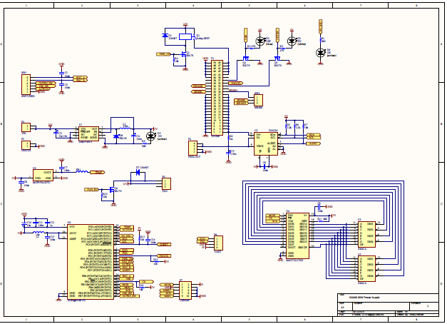
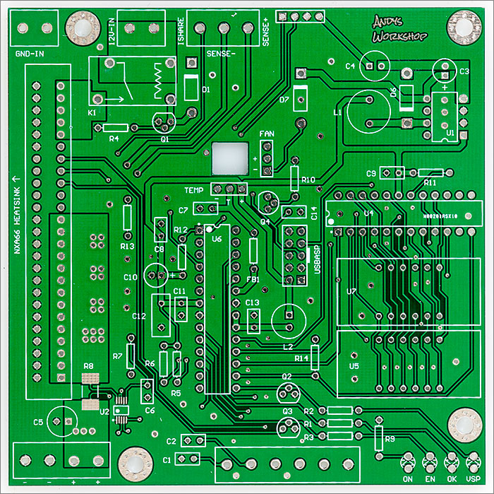
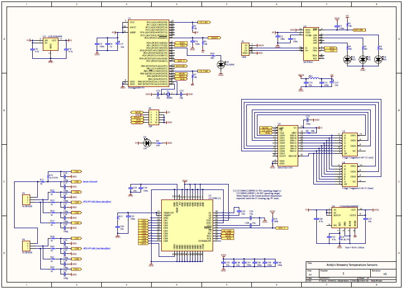
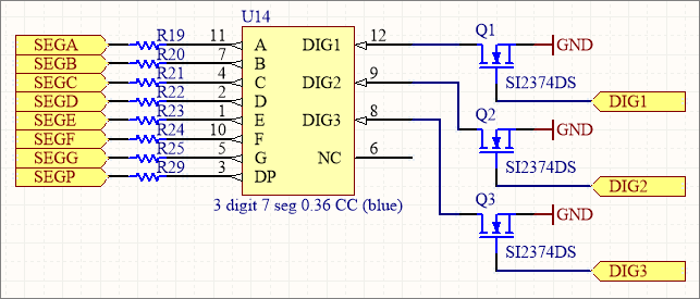
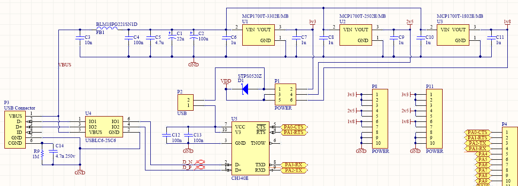
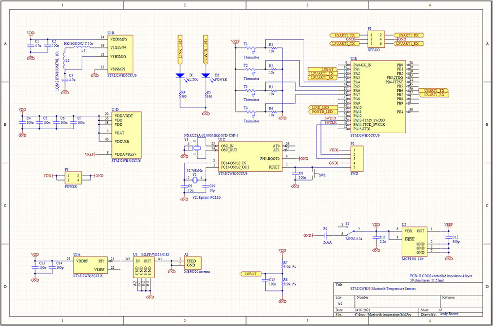
The schematic
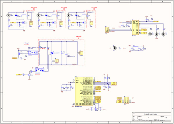
Now that I know the parts I’m going to use I’m going to create the schematic that links them all together. Click on the thumbnail to view a full-size PDF of this design.

Click on the thumbnail for a PDF
As you can see it’s quite a large one and is predictably dominated by the FPGA and the MCU. It’s much easier to follow if we break it down into modules. Let’s do that now.
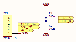
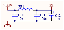
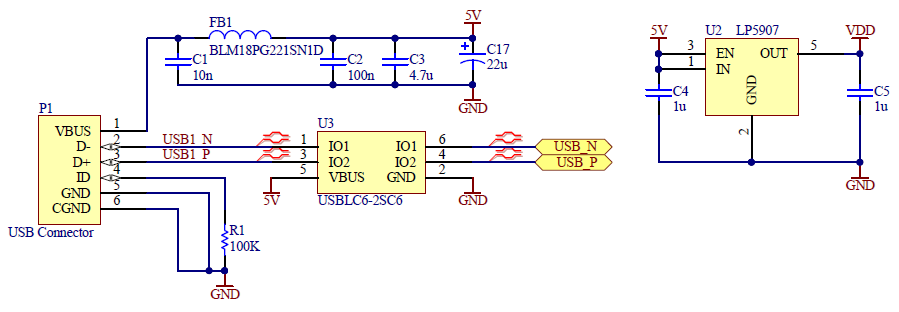
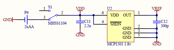
The power supply
Inputs to the main trio of regulators comes into a jack plug from an external 5V supply. The 2.8V supply is located physically far from the 5V input so it was more convenient to supply it from the 3.3V power line. The 10µF and 22µF smoothing capacitors are all tantalum and are all placed physically very close to the regulator that they are designed to work with.

C26, C18 and C23 are electrolytics that provide bulk low-frequency decoupling for the board. In one of Xilinx’s many design guides they recommend that every decade up to 100µF is covered by decoupling so I’m sticking to that recommendation here.
The 120Ω resistor from the 2.5V line to ground is another Xilinx feature. In XAPP453 Xilinx explain how to configure (program) an FPGA using a 3.3V MCU. One of the steps that must be taken is to include the 120Ω shunt resistor from 2.5V to ground to prevent the regulator from seeing a reverse current on its output pin. The downside of this requirement is that there will be a constant 20.8mA (50mW) drain even when nothing is happening.
It pays to study the thermal characteristics part of the voltage regulator datasheet. In my early experiments I was running this design with a 12V input instead of 5V. After running for some time I noticed that the system was spontaneously resetting itself. Odd, I thought, and then I touched the board. It was red hot around the AMS1117. The AMS1117 was going into thermal shutdown to protect itself from burnout and I went back to the datasheet to find out why.
In the thermal considerations section of the datasheet the formula for the power dissipation is given as PD = ( VIN – VOUT )( IOUT ). For my 12V input with a 400mA worst-case output that’s 3.48W of heat that’s going to be generated. Rather a lot. Going on to plug that figure into the formula for the maximum junction temperature gave me a figure of 233°C. The maximum allowed is 125°C. Hardly surprising that I was running into issues. By reducing the input voltage to 5V the power dissipation drops to a mere 0.68W and the maximum junction temperature to 65°C. Much better, and a valuable lesson learned.
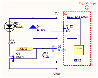
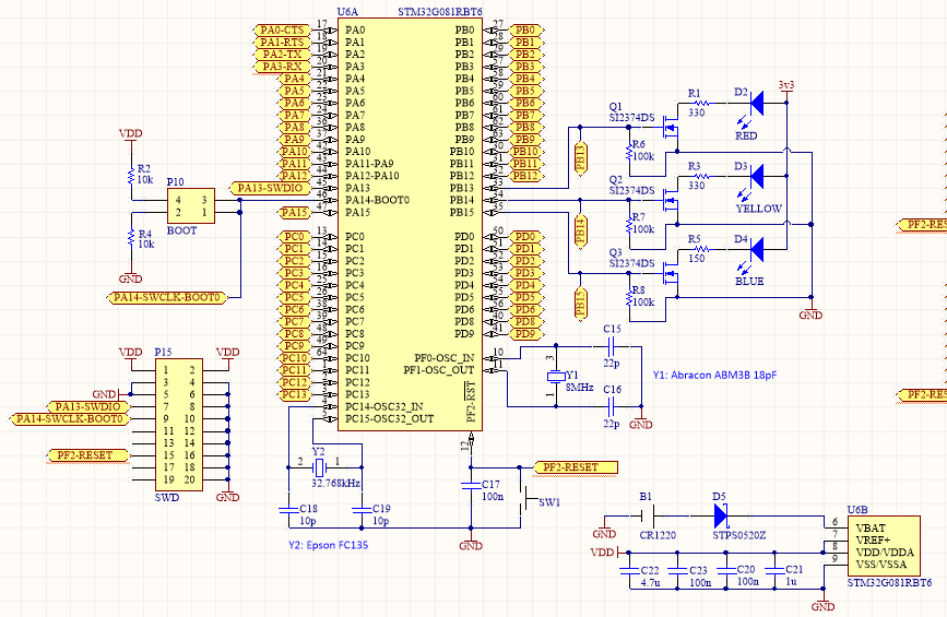
The FPGA
The FPGA is pictured here with its decoupling capacitors not shown to save space. If you want to see the decoupling network then please view the full PDF. The decoupling for the FPGA is quite substantial and attempts to follow the guidelines in Xilinx’s Power Distribution System (PDS) Design application note.

I’m using 62 out of the 63 available IOs in this design, only just squeezing in everything that I need. I chose the FPGA pins to be friendly to the ICs such as the SRAM, flash and the latch. The idea is that the components with high frequency signals will be placed very close to the FPGA and should require no board vias. This is meant to be a hobbyist-friendly design so it’ll be a 2 layer board and that means I must take care with the signal routing.
The SRAM is the greediest IC, requiring 28 IOs to cover its address, data and WE control signals. I’m saving 2 pins here by tying CS and OE both to ground as permitted in the SRAM datasheet.
The flash, being a SPI device is quite frugal in pin usage requiring only 6 pins in total. I can’t tie CS low with this device because CS is used in the SPI protocol to terminate certain command sequences.
The signal inputs from the MCU are the 10-bit data bus D0..9, the WR strobe and an active-high reset. The outputs to the MCU are the busy signal and a debug output that I used during development to set when certain states occurred. Debugging an FPGA in-circuit is about as hard as it gets folks.
All the programming signals, PROG_B, INIT_B, CCLK, DIN and DONE are all present and correct. I will be programming the FPGA using what Xilinx calls slave serial mode where an MCU clocks data into the FPGA and monitors the output signals to determine the success of the operation. The compiled .bit design is about 55Kbytes in size and takes a few tenths of a second to upload from the MCU.
I compile the .bit file in with the MCU program and load it into the FPGA on startup. For those that don’t know, an FPGA configuration is held internally in volatile SRAM so it’s lost when the power goes off and must be restored on system startup. (Some FPGAs do come with internal configuration storage flash memory but this family does not).
The LCD signals include the 8 bit data bus, the latch control line (LE) and the RS and WR lines. Going the other direction is the vital TE signal that will allow us to synchronise to the LCD frame output.
VCCO[0..7] are the 3.3V inputs, there’s one per FPGA IO bank. VCCINT are the 1.2V inputs and VCCAUX are the 2.5V inputs. This is a lot of power pins and associated decoupling capacitors and it only gets worse as you go up to larger FPGA packages. Another reason to stick with the small devices for hobbyist designs.
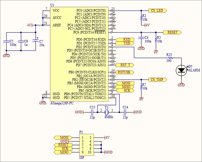
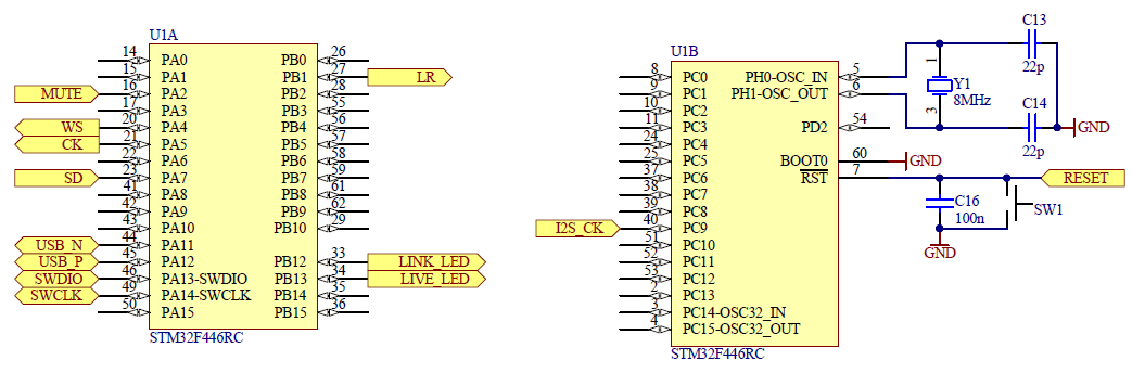
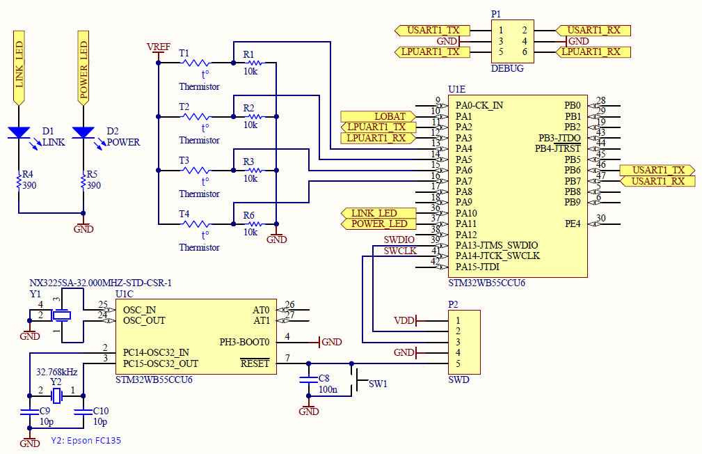
The MCU

The MCU is the counterparty to the FPGA in this design and you can easily see the opposing ends of some of the signals. For example I map the whole 10 bit data bus and the WR signal to port E. This will allow me to set the data and the WR strobe in a single port write. A reset button is provided just in case I need to externally reset the board at any time.
The SDIO signals map to the pins connected to the MCU’s SDIO peripheral so I can read and write to the SD card easily. The I2C SCL and SDA lines are connected to the I2C#2 peripheral inside the MCU and I’ve elected to provide two LEDs for status and other general purpose use. 18 of the GPIO pins are broken out to an external pin header so that I can add peripherals such as joysticks and other input devices for testing. The pins that are broken out are not done so at random, they are selected to cover a variety of the onboard peripherals that could be useful during development.
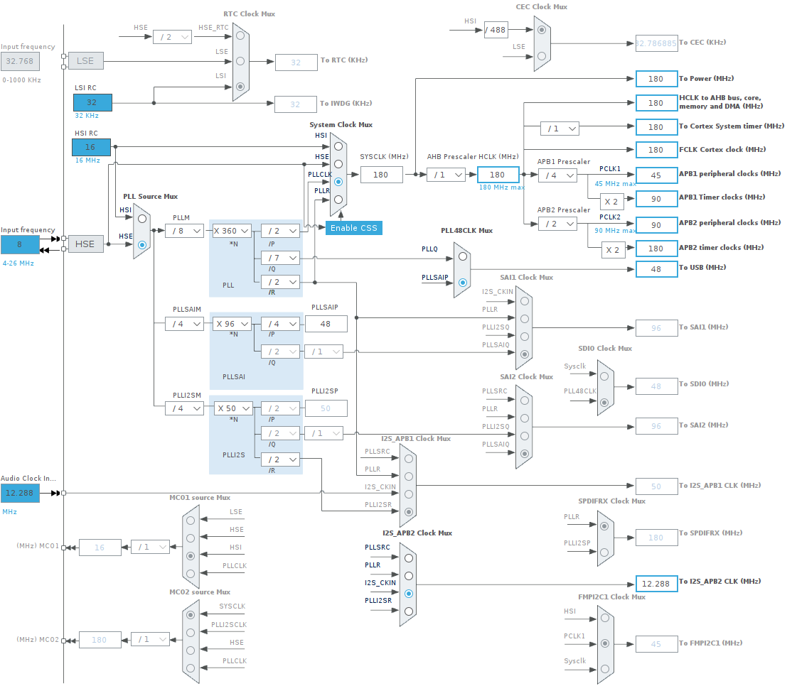
You may notice that that there’s no oscillator or quartz and that’s because this MCU doesn’t need one. As long as you can make do with 1% clock accuracy then you can use the internal 16MHz High Speed Internal (HSI) oscillator as the input to the PLL that generates the 180MHz core clock. 1% is fine by me and so I use the HSI.
After the complex requirements of the FPGA, the power supply for the MCU is a breath of fresh air. Decoupling (not shown in the screenshot) follows ST’s guidelines of a ceramic capacitor per-pin and a 4.7µF ‘chemical capacitor’ on the board. Electrolytics are chemical capacitors so that’s what I used. I prefer tantalums for their low ESR but didn’t have any to hand at the time.
Debugging and programming is done using SWD, a two wire protocol designed to replace JTAG as a more efficient design. SWDIO and SWCLK are broken out to a debug header on the board that can be directly connected to the cheap and effective ST-Link/v2 programming dongle.
The flash

The flash IC is the highest speed external peripheral on this board. The clock will run at 100MHz which is well into the territory where I could have signal integrity issues caused by overshoot, undershoot, reflections or any combination of the above if I’m not careful. For that reason all of the IO lines and the clock all feature 33Ω series termination resistors designed to sink reflections before they can harm the signal. These lines will also be kept very short on the PCB.
How did I decide on 33Ω? Rule of thumb I’m afraid. I don’t have the kind of equipment required to measure and select an ideal value so I’m starting at 33Ω and if I get problems then I’ll break out my bench oscilloscope and see whether I need to increase the resistance or not.
The SRAM

Memory ICs are not very exciting really. They’re just a pair of buses, a few control strobes and the power supply. To save on pins I’m connecting CS and OE directly to ground as permitted by the datasheet. I just need to control WE when I need to write data.
The address and data lines will change at a maximum of 50MHz in this design but the WE line will toggle at 100MHz. I’m not concerned about the address and data as long as I keep the lines short and without vias then 50MHz won’t be a problem. Writing this after the fact I do think that I should have at least put a footprint in for a 33Ω resistor on the WE line. If and when I produce another revision of the board then I think I’ll do just that.
The oscillator

An oscillator doesn’t need to be kickstarted by an external device and will start ticking from the moment it’s powered up. In my design I’ve elected to include a 33Ω series termination resistor on the clock line even though it’s probably overkill. This clock is so critical to everything else that I thought I’d be better safe than sorry.
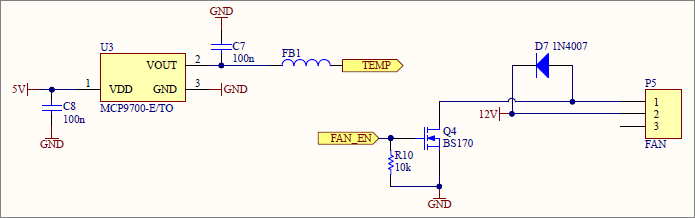
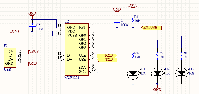
The LCD
The schematic for the LCD will be familiar to anyone that’s read either of my reverse engineering or my halogen reflow oven articles.

All of the control signals are connected to the FPGA except LCD_RES which is the reset signal. This one is connected to the MCU. There’s no need for us to bother the FPGA with the burden of the LCD reset sequence, this is best performed by the MCU.
The LCD backlight
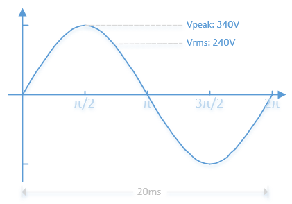
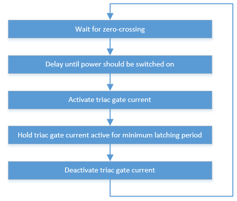
The backlight for this LCD consists of six white LEDS in series so we need a boost converter to generate the high voltage required to overcome the combined voltage drop of each LED.

The AP5724 from Diodes Inc. is a dedicated current-mode backlight driver that incorporates a boost converter. You only need to add a few external components including a current-setting resistor and the driver will then consistently output the selected current as long as the EN pin is driven high.
The cool thing is that we don’t even need to supply a PWM signal to the EN pin to control the backlight brightness because the LCD has a function to do that for us. All we need to do is tell the R61523 controller the duty cycle that we’d like to use and it’ll do the rest. That saves us a pin and a timer resource on the MCU.
The latch
The latch sits between the FPGA and the LCD, allowing us to use only 8 pins on the FPGA to drive a 16 bit data bus.

When LE is high the latch is transparent, data passes through from the D inputs to the Q outputs. A few nanoseconds after LE goes low the latch goes deaf to its inputs and continues to drive its outputs from the last data that it saw on those inputs.
What we do is write out the first 8 bits of data, lock the latch and then write out the second 8 bits. As you can see from the schematic this will result in all 16-bits being driven. What’s really helpful is that the FPGA design can be coded to output any bit to any pin so I can tailor the design so that the data bus can be laid out in parallel on the PCB without any vias.
The EEPROM
The EEPROM is an I2C device that provides some persistent storage for us.

The Rohm 32 Kbit IC has a simple 2-wire I2C interface. Nothing much to say here, it’s hooked up to the I2C peripheral on the MCU. I2C is a bi-directional single-wire bus that provides protection against being accidentally driven by multiple drivers by operating in open-drain mode. That means that the bus (and clock) must have pull-up resistors somewhere. I provide those 4.7kΩ pull-ups close to the MCU as you can see in the MCU schematic.
The SD connector
An ALPS SCHD3A0100 SD card cage is provided to house a micro SD card. The cage I’ve chosen accepts a slide-in SD card which is then locked into place by sliding it back a millimetre or so underneath a lip. Once in, it’s held securely and is not likely to fall out of its own accord.

I envisage that the graphics data will be much larger than I could program into the core of the MCU so some sort of external interface is required. SD cards are the most convenient way to do that and the MCU has a built-in SDIO peripheral that will allow me to access the card in the high-speed 4-bit mode. SDIO is another bus that requires pull-ups on its data and command lines, presumably because it’s also running in open-drain mode. I provide these 10kΩ resistors in the MCU schematic screenshot.
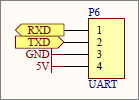
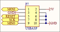
The pin headers
Two 2.54mm pin headers are provided for GPIO and debugging.

The pinout for the debug header matches the requirements published by ST Microelectronics for the SWD protocol and the ST-Link/v2 programmer/debugger. I’ve been really impressed with the ST-Link/v2. I use it all the time now with OpenOCD as the debug server and it’s never let me down.
The GPIO header breaks out a number of pins from the MCU for general purpose use. I’ve made sure that quite a few of the commonly used peripherals are covered including the I2S peripherals that I may use in the future for prototyping an audio capability.
Bill of materials
Here’s the full bill of materials for this project. There are, as you might expect, rather a lot of components. Nearly all are available at Farnell, my preferred local supplier and I’ve included links to their site where possible but you will have to venture further afield for a few of the other components.
A few of the components can be substituted for compatible devices from other manufacturers where something is available in the same footprint. Examples are U1, U2, U3, U12, L1, D1. Xilinx and ST both recommend low ESR capacitors for decoupling so choose the electrolytic and tantalum devices carefully.
| Designator | Value | Description | Footprint | Quantity | Farnell |
|---|---|---|---|---|---|
| C1, C2, C3, C5, C6 | 10µF | Tantalum capacitor | 1206 | 5 | 2353045 |
| C4 | 22µF | Tantalum capacitor | 1206 | 1 | 2333013 |
| C7, C8, C10, C13, C19, C24, C27, C28 | 100nF | Ceramic capacitor | 0402 | 8 | 1759380 |
| C14, C21, C22, C29, C31, C32, C33, C39, C40, C41, C44, C46, C47, C49, C50, C58, C59, C60 | 100nF | Ceramic capacitor | 0603 | 26 | 2211177 |
| C9, C12 | 10µF | Ceramic capacitor | 0805 | 2 | 2320852 |
| C11, C15, C34, C38 | 1µF | Ceramic capacitor | 0603 | 4 | 1759399 |
| C16 | 56pF 50V | Ceramic capacitor | 0603 | 1 | 1759063 |
| C17 | 56pF | Ceramic capacitor | 0603 | 1 | 1759063 |
| C18 | 100µF | Electrolytic capacitor | radial 2mm | 1 | 8767122 |
| C20, C25, C36 | 10nF | Ceramic capacitor | 0603 | 3 | 1759022 |
| C23 | 47µF | Electrolytic capacitor | radial 2mm | 1 | 2079293 |
| C26 | 4.7µF | Electrolytic capacitor | radial 2mm | 1 | 1236668 |
| C35 | 1µF 50V | Ceramic capacitor | 0805 | 1 | 1845750 |
| C37, C45, C48 | 2.2µF | Ceramic capacitor | 0603 | 3 | 1759392 |
| C42 | 4.7µF | Ceramic capacitor | 0603 | 1 | 2320811 |
| D1 | B0530W | Any compatible schottky | SOD123 | 1 | 1863142 |
| DEBUG | HDR2X10 | Header, 10-Pin, Dual row | 2.54mm | 1 | |
| L1 | 22µH | Inductor | 6x6x3mm | 1 | 1864120 |
| LCD | AXE534124 | Panasonic connector (Digikey US) | 17x2x0.4mm | 1 | |
| LED2 | Blue LED | LED, <3.3V Vf | 1206 | 1 | 2322084 |
| LED3 | White LED | LED,<3.3V Vf | 1206 | 1 | |
| P1 | HDR2X11 | Header, 11-Pin, Dual row | 2.54mm | 1 | |
| P2 | SCHD3A0100 | ALPS Micro SD connector | 2.54mm | 1 | |
| P3 | 2.1mm | PCB power jack | 1 | 2.1mm | |
| POWER | Red LED | Power indicator | 1206 | 1 | 2099256 |
| R1 | 120Ω | Resistor | 0603 | 1 | 2331714 |
| R2, R20, R21 | 390Ω | Resistor | 0805 | 3 | 2331790 |
| R3, R23, R24 | 4.7KΩ | Resistor | 0603 | 3 | 1469807 |
| R4, R7 | 68Ω | Resistor | 0805 | 2 | 2138823 |
| R5 | 330Ω | Resistor | 0603 | 1 | 2331721 |
| R6 | 5.1Ω 1% | Feedback resistor | 0805 | 1 | 2128935 |
| R8, R9, R14, R17, R22, R26, R27, R28, R29 | 10KΩ | Resistor | 0603 | 9 | 9238603 |
| R10, R11, R12, R13, R16, R18 | 33Ω | Resistor | 0603 | 6 | 9238301 |
| R25 | 1KΩ | Resistor | 0603 | 1 | 2073348 |
| RESET | PCB Button | Make type | 1 | ||
| U1 | TS1117BCP | 1.2V LDO regulator | TO-252 | 1 | 1476674 |
| U2 | AP1117E33G | 3.3V LDO regulator | SOT-223 | 1 | 1825291 |
| U3 | TS1117CW | 2.5V LDO regulator | SOT-223 | 1 | 7208340 |
| U4 | SN74ABT573APW | Octal latch | TSSOP-20 | 1 | 1740911 |
| U5 | XC3S50 | Xilinx Spartan 3 FPGA | VQ100 | 1 | |
| U6 | IS61LV5128AL | ISSI 512K x 8 10ns SRAM | TSOP2-44 | 1 | 1077676 |
| U7 | AP5724 | Diodes Inc. LED driver | SOT26A-6 | 1 | |
| U8 | ZXCL280H5T | Diodes Inc. 2.8V LDO regulator | SOT353-5N | 1 | 1461559 |
| U10 | S25FL127S | Spansion 128Mb serial flash | SOIC8 (208 mil) | 1 | 2328002 |
| U11 | STM32F429VIT6 | STM32 F429 MCU | LQFP100 | 1 | 2393659 |
| U12 | BR24G32FJ | Rohm 32Kb I2C EEPROM | SOP8 | 1 | 2373743 |
| X1 | FXO-HC375 | Fox 40MHz SMD oscillator | 1 | custom | 1641011 |
PCB design
I decided to target a low-cost 2-layer 10x10cm board of the sort that any hobbyist can afford to have printed at one of the Chinese prototyping houses. Routing it took a while. A long while.
The first component to go down was the LCD connector because it must physically sit in a specific place so that the LCD can be mounted on to the board in a position that allows the other connectors to be placed around it. The LCD connector is actually on the bottom of the board which, when sitting on my desk is facing upwards.
The next component to go down is the FPGA which I plonked down close to the center but mindful that I’d need to place another 100 pin device not far away.
After the FPGA the flash and the SRAM are placed as physically close to the FPGA as I dare and their IO traces are routed carefully.
Next to be routed are the FPGA power and decoupling traces. These traces are wider than most and the ceramic decoupling capacitors are placed as close to the FPGA pins as I can put them, and that meant using very small 0402 components for some of the pins. Others are decoupled on the opposite side of the board and use larger 0603 and 0805 packages.
Now that the components with specific requirements are down it was just a matter of placing the MCU in the best position I could find and routing the remaining signals. That part was not hard, just time consuming.
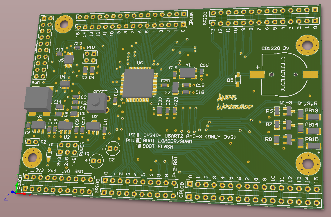
Final touches include a silk-screen logo, M3 mounting holes and some cool looking rounded corners on the PCB as a whole. The mounting holes are actually quite important because this board will be operated component-side down I will need stand-offs to provide the necessary clearance.
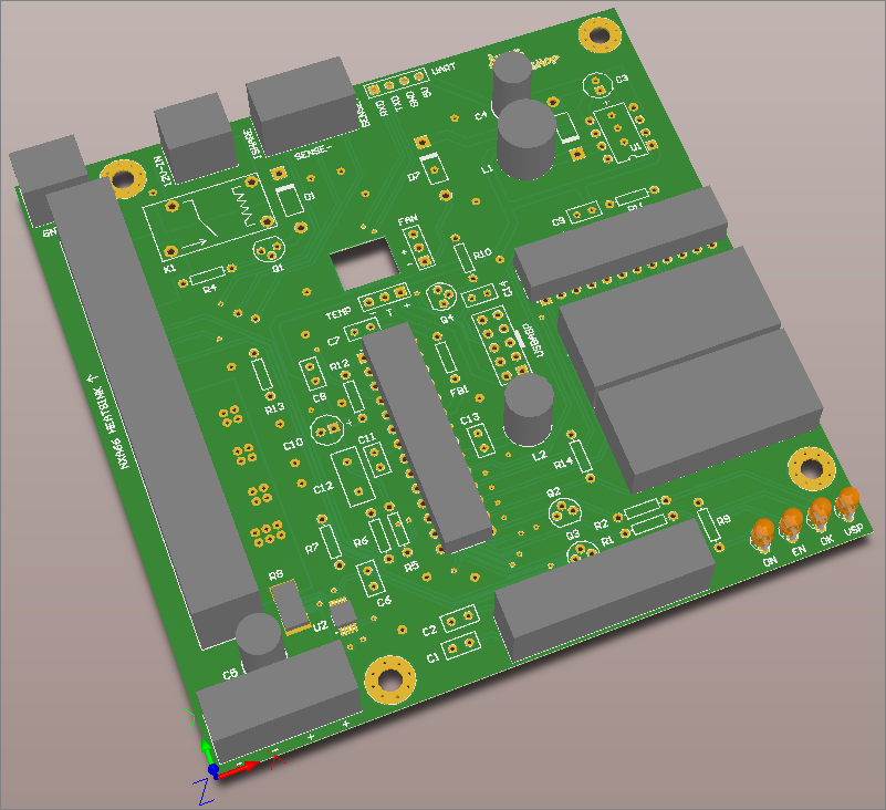
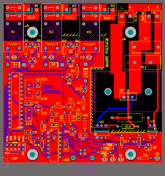
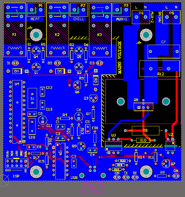
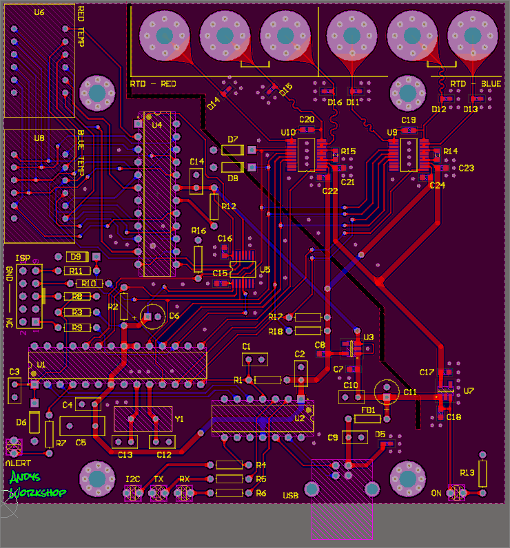
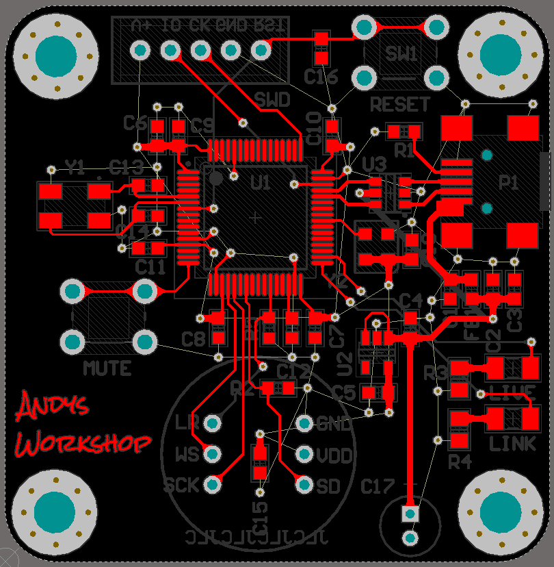
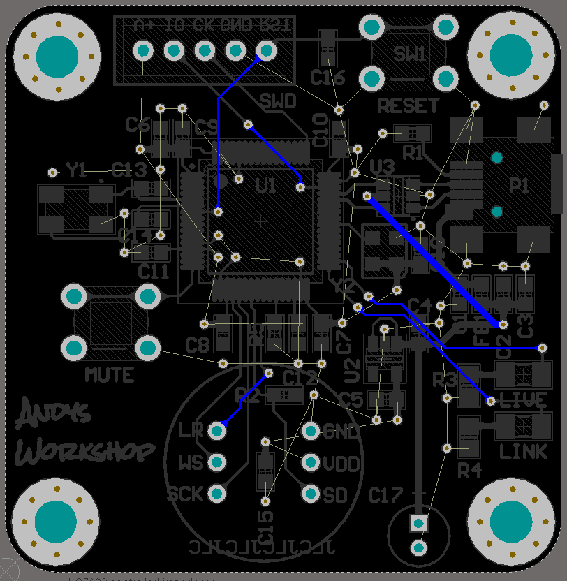
Let’s take a look at the routed PCB. I’ve hidden the ground pours on this screenshot to better show off the traces and components.

Click for a larger view
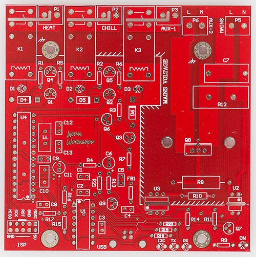
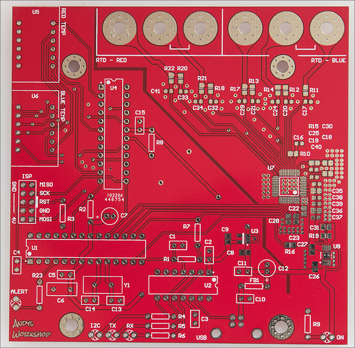
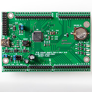
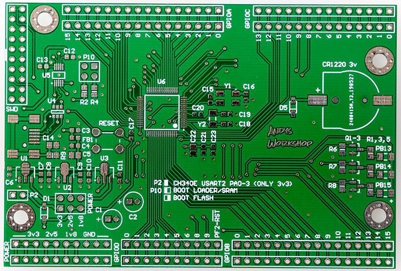
I elected to get the board printed at Elecrow, one of the many Chinese online services that’ll print you ten copies for a very reasonable price. About two or three weeks later the boards arrived in the mail and they look great!
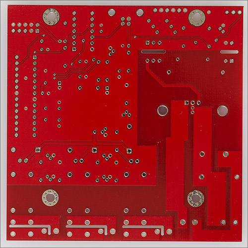
![]()
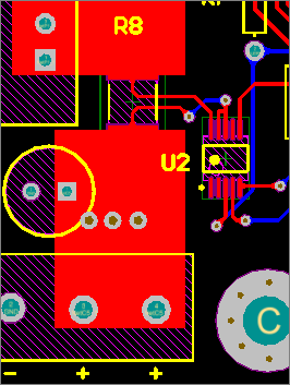
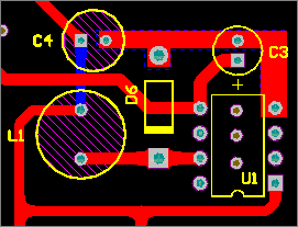
Click for larger
Note how the all the important traces from the FPGA go directly to their target ICs as a bus with no vias. One of the many beauties of working with an FPGA is that you decide the function of each pin and if you plan ahead then you can keep your board neat and tidy.
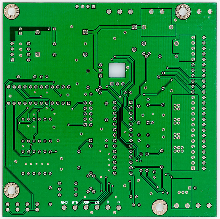
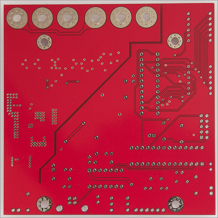
![]()
Click for larger
I inspected a PCB under a magnifying glass and could only find one issue, which was entirely my fault. The drill holes for the 5V power supply connector were too small by about 1mm. I’d mis-entered them into the footprint designer and not spotted it during any of my post-routing visual checks. Thankfully there was an easy solution to the problem, all I had to do was shave off about a millimeter from the legs on the power connector and I would be OK.
Assembling the PCB
Putting it all together required a bit of forward planning. I wanted to reflow the majority of the components using my halogen reflow oven but the problem was that the 34 pin, 0.4mm pitch LCD connector on the other side would also need reflow.
In the end it wasn’t so hard. I zoned off the area underneath the LCD connector that thankfully only housed a few small ICs for the backlight driver and reflowed the entire remainder of the component side in my reflow oven. For the second stage I turned the board over and reflowed just the LCD connector on my hot plate by holding the PCB with just the aforementioned zoned off area over the plate.
Now I could return to the zoned off area and reflow the remaining SMD components manually with my hot air gun. Finally the easy through-hole components were soldered into place with a regular iron. After a quick bath in white spirit to clean off the flux residues she’s ready for the photoshoot.

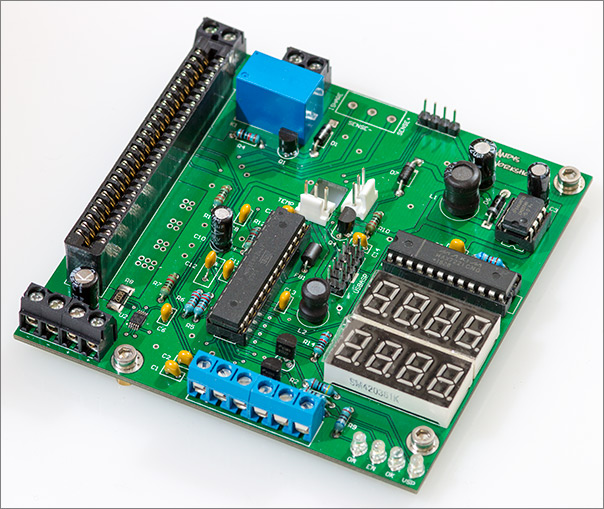
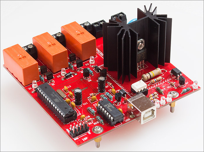
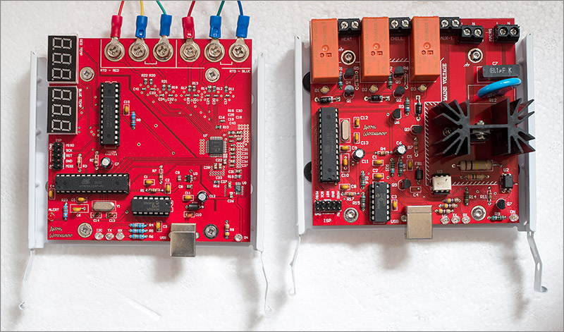
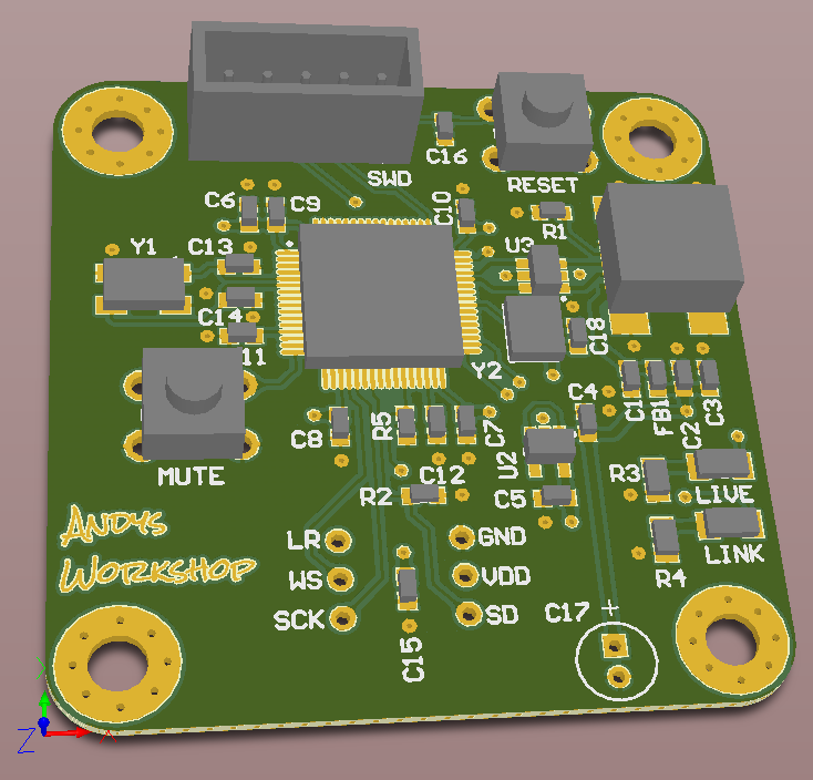
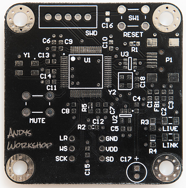
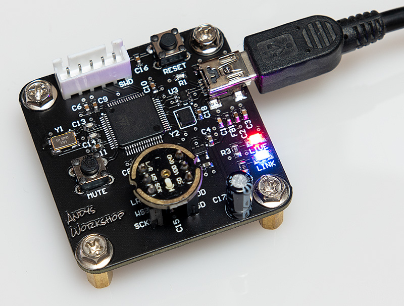
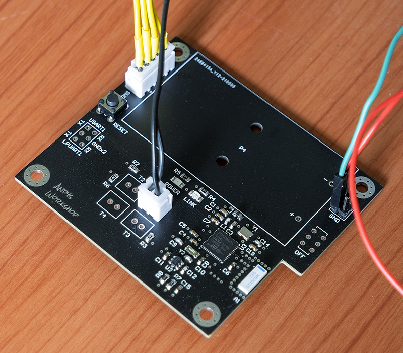
Click for larger
That’s the component side with everything in place. The reflow process in the oven, my first major project with the halogen oven, took care of everything very well but I still went around afterwards touching up joints here and there with my iron under the microscope.

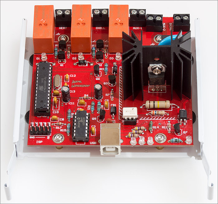
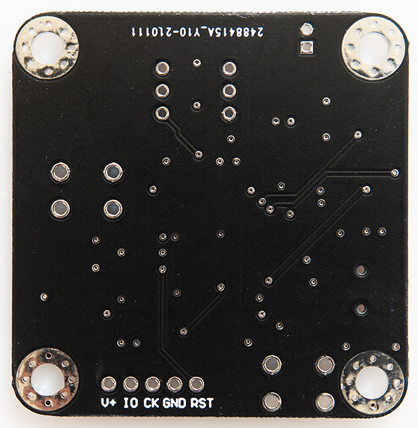
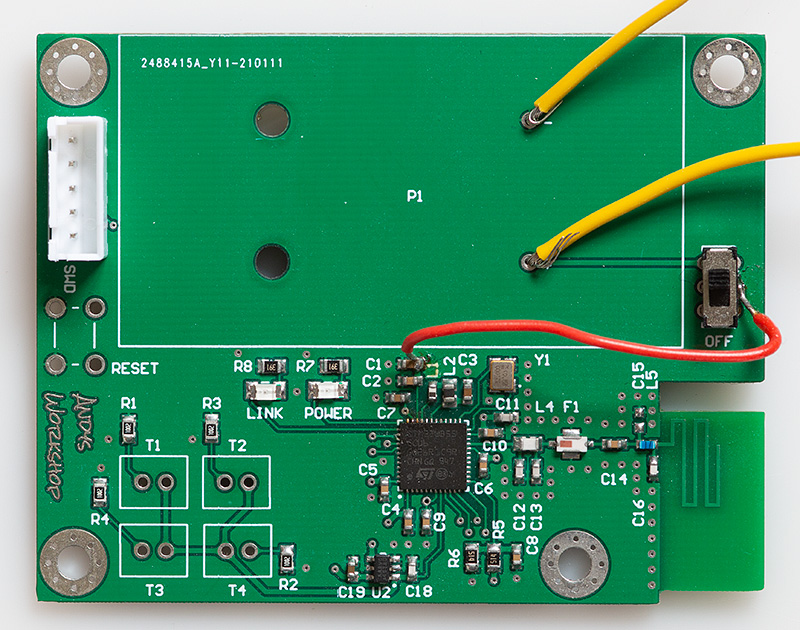
Click for larger
And the back side, which will actually be the topmost side when in use shown here before the LCD is attached. The array of decoupling capacitors that belong to the FPGA are clearly visible.

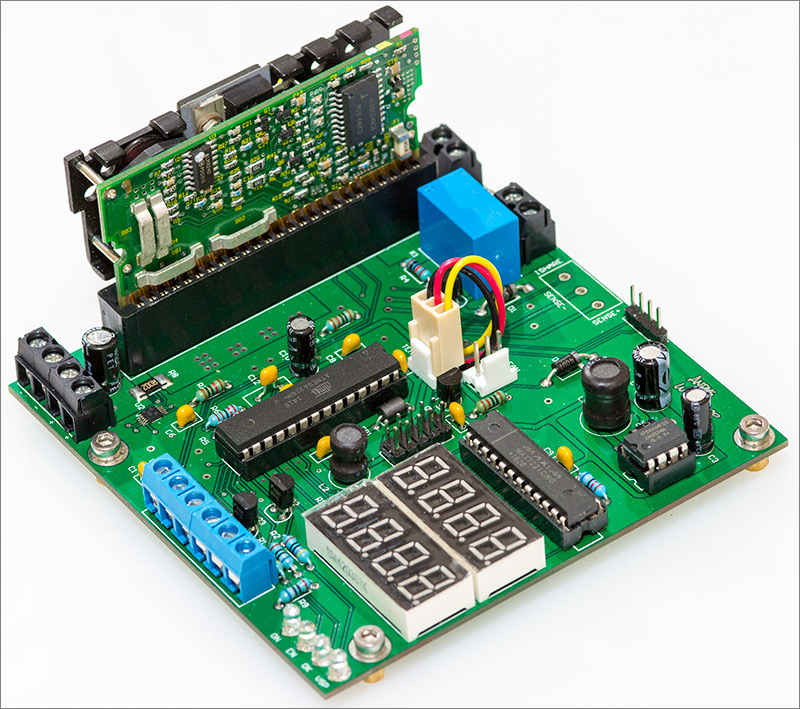
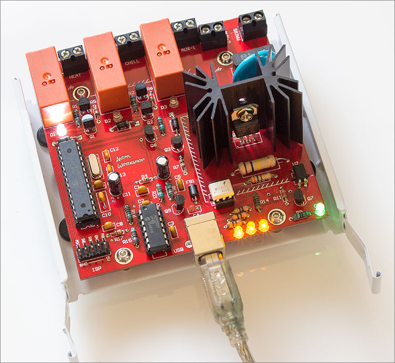
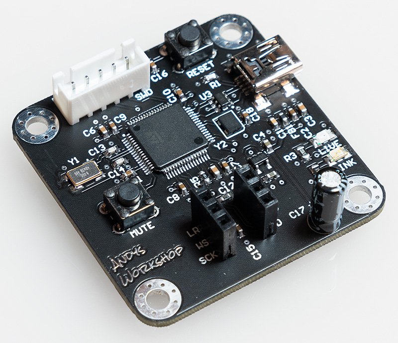
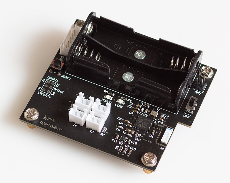
Click for larger
And the top side again, now with the LCD and 10mm standoffs in place. The LCD itself is held down and lifted clear of the PCB and the exposed capacitors with a set of double-sided sticky pads. The debug cable is shown in place, just missing that capacitor by a few millimetres (phew!).
Still with me? Great. The hardware was the easy bit, now I’m going to tackle the MCU firmware and the FPGA design. This should be fun.
Testing
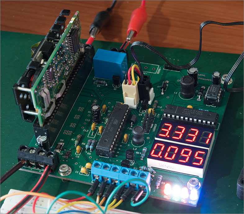
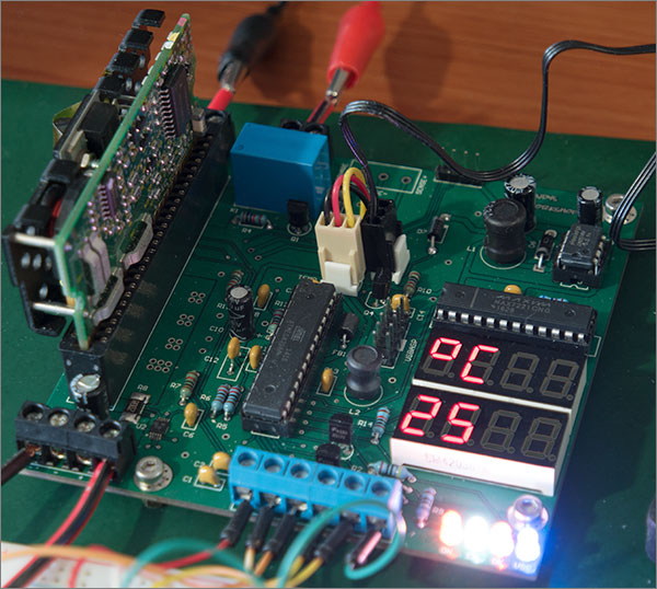
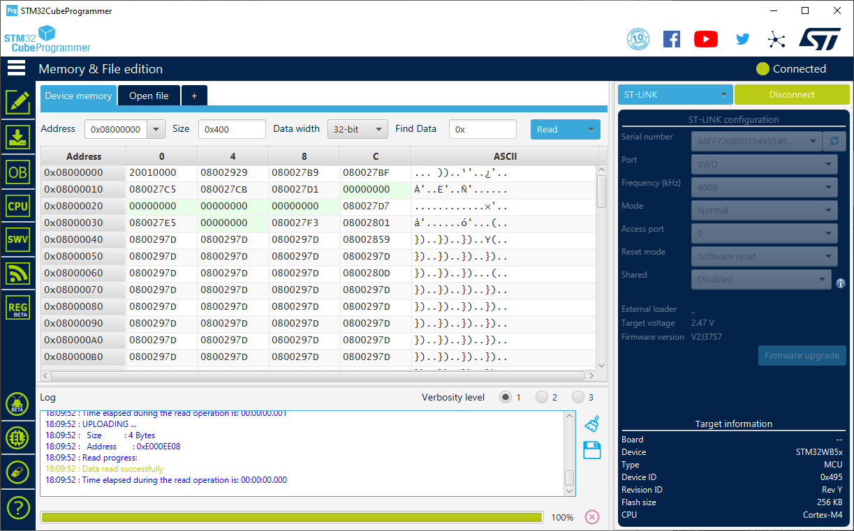
Obviously the first step in the testing phase is just to apply power, cross fingers and switch it on. The red power LED lit up. A little victory. Next we can see if the MCU’s alive by attaching the ST-Link/v2 dongle and seeing if I can connect to it with OpenOCD.
$ bin-x64/openocd-x64-0.7.0.exe -f scripts/board/stm32f4discovery.cfg
Open On-Chip Debugger 0.7.0 (2013-05-05-10:44)
Licensed under GNU GPL v2
For bug reports, read

http://openocd.sourceforge.net/doc/doxygen/bugs.html

srst_only separate srst_nogate srst_open_drain connect_deassert_srst
Info : This adapter doesn't support configurable speed
Info : STLINK v2 JTAG v17 API v2 SWIM v4 VID 0x0483 PID 0x3748
Info : Target voltage: 3.193738
Info : stm32f4x.cpu: hardware has 6 breakpoints, 4 watchpoints
As you can see I’m using the pre-canned script that sets the interface and target MCU as if it were an F4 discovery board and we have a complete success, the MCU should now be programmable.
MCU test code
I wrote a number of small test programs to check out the various features on the board and you can see them all on github. They all make use of my stm32plus library to take the heavy lifting out of working with the STM32 peripherals. Although the stm32plus library does not directly support the F42x line it’s quite OK to use the supported F40x build, you just won’t get any support for the additional peripherals on the F429.
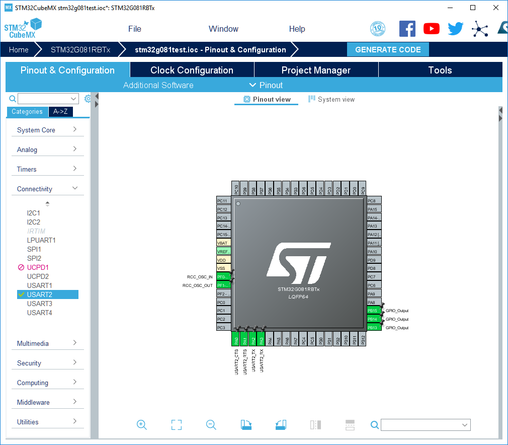
      GpioD<DefaultDigitalOutputFeature<10,11> > pd;

      // loop forever switching it on and off with a 1 second
      // delay in between each cycle

      for(;;) {

        pd[10].reset();
        pd[11].set();
        MillisecondTimer::delay(1000);

        pd[10].set();
        pd[11].reset();
        MillisecondTimer::delay(1000);
      }
An alternate on-off blinker for the two LEDs
 One small hurdle that I had to overcome was the issue of the startup code and setting the core clock to 180MHz using only the internal oscillator. After reset and before main() executes every STM32 program goes through a small routine to configure the device’s clock tree and set the speeds of the various buses.
I couldn’t find any sample ST initialisation code for the F429 using the high-speed internal (HSI) 16MHz clock as the system clock source. They do provide an Excel spreadsheet that supports the F40x devices so I took that as the starting point and adjusted the PLL multiplier accordingly to generate the 180MHz core clock. I couldn’t resist tidying up ST’s code – if you’ve ever seen any ST-authored ‘C’ code then you’ll know what I’m talking about! Click here to view the startup code on github.
/*
 * These are the key constants for setting up the PLL using 16MHz HSI as the source
 */

enum {
  VECT_TAB_OFFSET = 0,      // Vector Table base offset field. This value must be a multiple of 0x200.
  PLL_M           = 16,     // PLL_VCO = (HSE_VALUE or HSI_VALUE / PLL_M) * PLL_N
  PLL_N           = 360,
  PLL_P           = 2,      // SYSCLK = PLL_VCO / PLL_P
  PLL_Q           = 8       // USB OTG FS, SDIO and RNG Clock =  PLL_VCO / PLL_Q (note 45MHz unsuitable for USB)
};
One-by-one all the peripherals checked out fine. GPIO, EEPROM and crucially SDIO all worked without any problems. I’ve got to tell you, I was pleased at this point despite not even having looked at the FPGA yet. Talking of which…
Configuring the FPGA
 Configuring an FPGA is analogous to programming an MCU. You take your compiled work and operate a manufacturer-defined protocol to get it on to the device whereupon the device is able to start doing what you intended it to do. Where FPGAs differ from MCUs is that their configuration is volatile, that is when you turn off the power it’s gone so you have to reconfigure it every time you boot up the power.
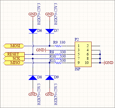
Xilinx FPGAs offer a wide range of configuration methods with excellent documentation. The method that I’ve chosen is called slave serial and it requires an external device (the MCU) to bit-bang the compiled configuration using a serial stream. Here’s an image from the Xilinx documentation that shows a potential configuration circuit, slightly modified by me to remove the JTAG pins because I’m not using those.

The only problem is that the configuration interface on the FPGA is powered by the VCCAUX 2.5V supply and the MCU is powered by the 3.3V supply. Luckily Xilinx have thought of that one and have produced another excellent reference document that tells us what we need to do to configure the FPGA safely from a 3.3V MCU.

The full meaning of the additional parts is very well explained by Xilinx but to quickly summarise, they’ve inserted some current limiting resistors and a shunt resistor next to the 2.5V regulator to drain away excess current so the regulator is prevented from seeing a potentially damaging reverse current on its output pin.
Configuration performance considerations
The compiled and uncompressed bit file for the XC3S50 is about 440096 bits give or take. The maximum speed that Xilinx allows me to operate the serial data line is 66MHz which reduces to 20MHz with compression. You can find these limits documented in the main datasheet under the specifications for FCCSER.
My design is going to almost fully utilise the FPGA so the rudimentary run-length compression supported by the FPGA is of no use to me and I’d prefer to take advantage of that 66MHz maximum clock. Theoretically I can program the FPGA in 440096/66000000*1000 = approx 7ms. In practice I have the additional overhead of shifting the bits for output and monitoring the INIT_B and DONE pins for status changes so in the end the debug build of the firmware can program the device in about half a second.
You can see the source to the configuration class here on github. It relies on the bit file being compiled into flash with the MCU program and you can see how I do that here on github.
Testing the FPGA
Now I have the means to configure the FPGA I need to stretch its legs a bit to check out whether my home manufacturing process has been a success. Naturally, that’s going to involve a blink test, the hardware equivalent of Hello World.
Xilinx development
Back when I decided to teach myself a hardware description language (HDL) the choice of available languages came down to two options: VHDL or Verilog. VHDL was touted as looking a bit like Pascal (ask your Dad) or Ada (ask your Grandad). Verilog was touted as looking a bit like ‘C’ (it doesn’t). I rather liked the rigorous and verbose looking syntax of VHDL and and so, since there’s no difference in the capabilities of each language, I chose VHDL. Professional FPGA engineers are likely to know both.
Xilinx offers a free development environment that they call the ISE Webpack that somehow manages to require 17Gb of space on my SSD. The tools offered by the webpack are both comprehensive and confusing in equal measure. As a beginner you’ll want to use an IDE to introduce you to the workflow and you’ll get a choice of two from Xilinx.
ISE Design Suite is the first option and the one I recommend for beginners. It appears to be written in a language that compiles to native code so it’s quite efficient and doesn’t consume many resources itself while the synthesis tools are running.

The ISE project navigator clearly shows the synthesis workflow and has an easy to use interface for creating and running simulations. It’s particularly useful for determining the availability and meaning of the many command line options that you can use.
The second option is to create your project using their Plan Ahead tool. I don’t recommend this. Plan Ahead appears to be written in java and as such it takes a heavy toll on your resources while synthesis is running. On a low powered laptop I caught it using 100% of a CPU core presumably just monitoring the tool output files for changes. However, Plan Ahead is fine for IO pin planning and is actually very useful for that task because it allows you to visualise the package while choosing pins.
I started out some time ago using ISE Design Suite and once I’d got the hang of the workflow and the command line options I dropped it in favour of a command line build environment using my favourite text editor and the scons build system. This project does not use the ISE GUI.
Xilinx command line builds
The one area where Xilinx seems to have gone completely off the rails is the ability to operate the tools from the command line in harmony with a source control system. The tools will spew literally dozens of output, intermediate and report files and subdirectories into your source directory. You can see the rules I have to create in the SConscript and .gitignore files just hide this garbage.
Furthermore, the coregen.exe utility commits the cardinal sin of modifying its input source file when you run it making git think it’s always been modified. You have to ask yourself whether the teams that wrote these tools actually use source control themselves.
FPGA blink
Here’s an implementation of blink on the FPGA in VHDL.
library IEEE;
use IEEE.STD_LOGIC_1164.ALL;
use IEEE.numeric_std.all;

entity blink is
port(
  clk     : in  std_logic;
  led_out : out std_logic
);
end blink;

architecture behavioural of blink is
 constant clock_count : natural := 80000000;      -- 2x clock frequency in Hz
begin

  process(clk)
    variable count : natural range 0 to clock_count;
  begin

    -- for half the time led_out = 0 and 1 for the other half

    if rising_edge(clk) then
      if count < clock_count/2 then
        led_out <='1';
        count := count + 1;
      elsif count < clock_count then
        led_out <='0';
        count := count + 1;
      else
        count := 0;
        led_out <='1';
      end if;
    end if;
  end process;

end behavioural;
This is a synchronous design with the sole process synchronised to the 40MHz oscillator via the clk signal. Each time the oscillator ticks a counter is increased and after a second the led_out signal is toggled.
My FPGA is not connected to an LED so I routed led_out to the DEBUG pin and used a logic analyser to verify the ticking. It worked, which told me that the FPGA was up and running, was being correctly programmed via the MCU and that at least two of the pins worked and the oscillator was ticking. A small design proved out a large part of the board.
Programming the flash
If you review the schematic you’ll see that the flash IC is only connected to the FPGA and not the MCU therefore I needed to create an FPGA design for programming it. A simple approach would have been to configure the FPGA to just pass through all signals from the MCU to the flash. The FPGA would function as little more than a buffer and all the logic would be in the MCU.
The second option would be to operate the flash programming logic from within the FPGA, accepting commands and data to be programmed from the MCU. This was the more complex option but I was up for the challenge and set about doing it this way.

The diagram shows the workflow involved in programming the flash. At a high level the MCU reads pre-formatted graphics from the SD card and then writes them one by one to the FPGA and then verifies that each one has been written correctly. The actual steps involved are:
- This design runs at a relatively pedestrian 40MHz so I set the non-volatile flash configuration register (CR) to the default speed setting and disable the bit that enables the quad IO mode.
- I issue the command to erase the entire flash device and wait for the FPGA to de-assert the
BUSYpin that indicates the operation is complete. The FPGA polls the flash status register for this flag. It takes the flash about 30 seconds to complete a full erase operation. - One by one I program each of the files on the SD card into the flash device by issuing block program instructions for each 256 byte page.
- I go back and get the FPGA to verify each of the files. I re-supply the file data for each block and the FPGA reads the block from the flash, compares it and asserts the
DEBUGpin if there’s a discrepancy. - I set the bits in the configuration register that enable the flash to operate at 100MHz and I enable quad output mode in the assumption that the main sprite accelerator will be the design that runs next.
The source code for all this is available on github. The MCU program is here and the FPGA design is here. I’d simulated this design before writing the MCU code so I was sure that the logic was OK and so it did more or less work first time. The only glitch I had to iron out was sampling the asynchronous WR line in the FPGA. FPGAs really don’t like asynchronous signals and you have to take extra steps to avoid metastability when sampling an asynchronous pin.

Click for larger
I really can’t emphasize enough how hard it is to debug an FPGA in-circuit so it’s imperative that designs are thoroughly simulated up-front. My in-circuit debugger consists of a single output pin that I can set or reset depending on some internal state.
The main design
The main VHDL design is broken down into components linked together by their input and output signals. In FPGA lingo they call this a hierarchical design and if you’re accustomed to any modern programming language it’ll feel completely natural to you as opposed to dumping the whole design into one file (yes, they do that too).

main is the overall container that declares the I/O port that maps directly to the pins on the VQ100 package. Main is responsible for instantiating the rest of the components and linking together their inputs and outputs. Let’s take a brief look at the purpose of each component.
mcu_interface
The FPGA is connected to the MCU via a 10-bit data bus and an asynchronous WR strobe. The MCU writes data on to this bus and then pulses WR low and then high again. The FPGA reacts to the rising edge of WR by writing the 10-bit value into an internal 64-entry FIFO implemented in distributed RAM.
At the same time, mcu_interface is also reading data off the other end of the FIFO and when it’s read enough parameters to execute the desired command it will spend a few 10ns cycles executing that command before returning to reading more data off the FIFO.
It’s up to the MCU to ensure that it doesn’t write data to the FIFO faster than the FPGA can read it off. In practice this is not likely as the MCU is likely to have to spend some time executing logic between each command during which time the FPGA will be draining the FIFO and executing commands.
The actual commands that I’ve implemented allow the MCU to write raw data to the LCD in passthrough mode, put the FPGA into sprite mode and execute commands to load, move hide and show sprites. You can see the documentation for the commands here on github.
sprite_writer
This is the big one. sprite_writer is responsible for reading sprite definitions from the internal block RAM (BRAM), reading the graphics from the flash IC and writing them to the correct locaton in the SRAM frame buffer.
The outer loop of this component iterates through each of the 512 sprite definitions acting on each one that has the visible bit set to true. For each visible sprite there are then two inner loops that handle the X and Y repitition counters that allow a sprite to be output into a grid pattern on the display.
Inside the X/Y repitition counter there is the main loop that reads data from the flash and writes it to the SRAM. This is the timing-critical part as there are only 4 cycles (40ns) available to completely process each pixel. The loop operates a sort of pipeline where each iteration writes out the previously read pixel to the SRAM while simultaneously reading the next pixel from the flash. Pixel transparency is handled and the internal logic that allows sprites to be partially visible is taken care of.
sprite_writer instantiates a couple of internal components for its own use. Those with a conventional programming background may find it surprising that the things they take for granted such as addition, subtraction and even counting do not necessarily come for free with an FPGA. If you want to add two numbers then you’ll need to implement an adder. Want to multiply? That’ll cost you a multiplier. In these days of virtual machines and interpreted languages it’s refreshing to know that little has changed at the fundamental level since I started a long time ago.
This has not gone un-noticed by the FPGA manufacturers who in many models offer hard implementations of adders and multipliers (sometimes touted as DSP primitives) distributed throughout the chip fabric. The adders that I instantiate are pipelined implementations that take less of a chunk out of my timing budget than those that xst infers if I just use the VHDL + operator.
The memorably named OFDDRSSE component is one of a family of OFDDR primitives that allow you to output a clock to an IOB (a package pin). You might think that you can just hook up an internal clock signal to an output, or maybe gate a clock with some internal logic and output that signal to an IOB. That would be naiive because it would create a high level of skew between the output clock and your design. Clocks in an FPGA are treated like royalty and there’s always a correct way to do the common clock operations. Using an OFDDR primitive is the correct way to output a clock signal to a pin and I use it to create the 100MHz flash clock with the CE clock-enable input used to switch the clock on and off.
frame_counter
In the initial design I explained how I was going to use even frames to write data from the SRAM to the LCD and odd frames to load up the SRAM from the flash. frame_counter monitors the LCD TE signal and each time it spots a rising edge it flips the bit that indicates odd or even frames.
TE is an asynchronous signal so a simple shift register is used to sample the current state and use the two previous states to check for sure if there has been a rising edge.
lcd_sender
lcd_sender is a utility component that outputs a 16-bit value to the LCD data bus, taking care of the interaction with the latch and the correct timing for the LCD WR strobe. I call it from mcu_interface when the design is in passthrough mode and I need to write out a value from the MCU to the LCD. It takes exactly 70ns to execute and has a ‘busy’ output signal and a ‘go’ input signal to allow synchronisation with its operation.
sprite_memory
sprite_memory is an instantiation of the Xilinx BRAM IP core. Block RAM on this FPGA is a true dual-port RAM with configurable data and address bus widths. I use it to store sprite definitions. Here’s the definition of a sprite record:
  -- subtypes for the various bit vectors

  subtype bram_data_t       is std_logic_vector(126 downto 0);
  subtype sprite_number_t   is std_logic_vector(8 downto 0);
  subtype flash_addr_t      is std_logic_vector(23 downto 0);
  subtype sram_pixel_addr_t is std_logic_vector(17 downto 0);
  subtype sram_byte_addr_t  is std_logic_vector(18 downto 0);
  subtype sram_data_t       is std_logic_vector(7 downto 0);
  subtype sprite_size_t     is std_logic_vector(17 downto 0);
  subtype sprite_width_t    is std_logic_vector(8 downto 0);
  subtype byte_width_t      is std_logic_vector(9 downto 0);
  subtype sprite_height_t   is std_logic_vector(9 downto 0);
  subtype pixel_t           is std_logic_vector(15 downto 0);
  subtype flash_io_bus_t    is std_logic_vector(3 downto 0);

  -- structure of a sprite in BRAM
  -- total size is 127 bits

  type sprite_record_t is record

    -- physical address in flash where the sprite starts (24 bits)
    flash_addr : flash_addr_t;

    -- pixel address in SRAM where we start writing out the sprite (18 bits)
    sram_addr : sram_pixel_addr_t;

    -- size in pixels of this sprite (18 bits)
    size : sprite_size_t;

    -- width of this sprite (9 bits)
    width : sprite_width_t;

    -- number of times to repeat in the X-direction (9 bits)
    repeat_x : sprite_width_t;

    -- number of times to repeat in the Y-direction (10 bits)
    repeat_y : sprite_height_t;

    -- visible (enabled) flag (1 bit)
    visible : std_logic;

    -- firstx is the offset of the first pixel to be displayed if the sprite is partially off the left
    firstx : sprite_width_t;

    -- lastx is the offset of the last pixel to be displayed if the sprite is partially off the right
    lastx : sprite_width_t;

    -- firsty is the offset of the first pixel to be displayed if the sprite is partially off the top
    firsty : sprite_height_t;

    -- lasty is the offset of the last pixel to be displayed if the sprite is partially off the bottom
    lasty : sprite_height_t;

  end record;
Since my record is 127 bits long I configure the BRAM to have a 127-bit data width. The address bus must of course be a power of 2 wide so that means I can fit 512 sprite definitions into the BRAM on this FPGA.
frame_writer
frame_writer is the component responsible for doing all the work during the even frames when the FPGA is in sprite mode. It reads the rendered frame from SRAM and writes it out to the LCD. It operates a pipeline, reading out a pixel from SRAM and writing the previously read pixel to the LCD simultaneously during a core 70ns loop. There are 640×360 = 230,400 pixels on the display which means that this whole operation takes exactly 16.128ms. The LCD is reading from its internal GRAM and writing to the physical display at a rate of one every 16.2ms so we come in just within the required timing.
frame_writer does impose a few small requirements on the MCU before sprite mode is engaged. The display window must have been set to the full screen, the write mode must have been set to auto-reset to the start of the display window and the last LCD command to have been sent must be the ‘write data’ command. With this prep done by the MCU the FPGA can just let rip with the continual flow of graphics data. My AseAccessMode class takes care of all this.
lcd_arbiter
My decision to support passthrough and sprite modes means that there are potentially two different parts of the design that want to write data to the LCD bus. mcu_interface will write data via the lcd_sender class in passthrough mode and frame_writer will want to write data when we’re in sprite mode.
It makes no sense to have multiple drivers attempting to connect to the same signal and the synthesis tool will flag it up as an error if you try. The answer is to have an arbitration process that inspects a state variable and connects up the output according to that state.
architecture behavioral of lcd_arbiter is

begin

  process(clk100) is
  begin

    if rising_edge(clk100) then

      if mode = mode_passthrough then
        lcd_db <= lcd_sender_db;
        lcd_wr <= lcd_sender_wr;
        lcd_ale <= lcd_sender_ale;
        lcd_rs <= lcd_sender_rs;
      else
        lcd_db <= frame_writer_db;
        lcd_wr <= frame_writer_wr;
        lcd_ale <= frame_writer_ale;
        lcd_rs <= '1';
      end if;

    end if;

  end process;

end behavioral;
As you can see it’s a really simple job to do the arbitration.
reset_conditioner
resets, like clocks, have a special place in the heart of the FPGA designer and everyone’s got an opinion on how to best implement a reset. The current thinking, which I tend to agree with, is that reset should be a synchronous signal and that it should only be an input to components that actually need it. Don’t waste space and un-necessarily increase the signal’s fanout by hooking it into a component that doesn’t need to be reset.
Reset is a drastic operation that you don’t want to happen by accident so reset_conditioner implements a slightly longer and more rigorous shift register to ensure that the asynchronous signal from the MCU has been correctly asserted before supplying its own synchronous conditioned output that gets routed to all the components that have something to do upon reset.
clock_generator
Earlier FPGAs from Xilinx always had a PLL on board that you could use to multiply up a clock input to give you a higher frequency for operating the synchronous parts of your design. Xilinx have significantly improved that facility and now they provide multiple Digital Clock Manager (DCM) primitives. The DCMs are highly flexible clock conditioning and synthesis primitives. You can perform all kinds of phase adjustment, clock doubling, multiply/divide synthesis all with guaranteed low skew synchronised outputs.

The above diagram is taken from the Xilinx datasheet and shows the structure of a DCM. My design runs at an internal frequency of 100MHz so I use the CLKFX clock synthesis facility to multiply and divide the 40MHz input to get that 100MHz target.
  inst_clock_generator : clock_generator port map(
    clkin_in        => clk40,
    clkfx_out       => clk100,
    clkfx180_out    => clk100_inv,
    clkin_ibufg_out => open,
    clk0_out        => open
  );
Not so obvious is that I need to use the CLKFX180 output to receive a 100MHz signal phase-shifted by 180°. This signal is required as an input to the OFDDRSSE component that reconstructs the 100MHz clock for output to the flash IC. I’m guessing that it’s used so that the internal logic can just trigger on rising clock edges.
FPGA resource utilisation
A succesful FPGA design must meet its area and timing constraints. Meeting the area constraint simply means that all your logic has to fit in your chosen device. If it doesn’t then there are tricks and optimisations that you can apply but if they don’t work then your only option might be to step up to the next larger device in the range and that can be expensive. Here’s my area utilisation results:
Device utilization summary:
---------------------------

Selected Device : 3s50vq100-5

 Number of Slices:               795  out of    768   103% (*)
 Number of Slice Flip Flops:     875  out of   1536    56%
 Number of 4 input LUTs:         1406  out of   1536    91%
    Number used as logic:       1326
    Number used as RAMs:          80
 Number of IOs:                   61
 Number of bonded IOBs:           61  out of     63    96%
 Number of BRAMs:                  4  out of      4   100%
 Number of GCLKs:                  3  out of      8    37%
 Number of DCMs:                   1  out of      2    50%
I like to get value for money out of my kit so a healthy 103% usage is a good result. But wait, didn’t I say that you couldn’t over-utilise? Yes I did but these stats are just an estimate from xst, the synthesis tool. The important tool, map, is the one that fits the compiled design to the device and tries to optimise it. I use map with the ‘try really hard please’ flag set and get these results:
Design Summary
--------------

Design Summary:
Number of errors:      0
Number of warnings:   14
Logic Utilization:
  Number of Slice Flip Flops:           913 out of   1,536   59%
  Number of 4 input LUTs:             1,375 out of   1,536   89%
Logic Distribution:
  Number of occupied Slices:            760 out of     768   98%
    Number of Slices containing only related logic:     760 out of     760 100%
    Number of Slices containing unrelated logic:          0 out of     760   0%
      *See NOTES below for an explanation of the effects of unrelated logic.
  Total Number of 4 input LUTs:       1,449 out of   1,536   94%
    Number used as logic:             1,286
    Number used as a route-thru:         74
    Number used for Dual Port RAMs:      80
      (Two LUTs used per Dual Port RAM)
    Number used as Shift registers:       9

  The Slice Logic Distribution report is not meaningful if the design is
  over-mapped for a non-slice resource or if Placement fails.

  Number of bonded IOBs:                 61 out of      63   96%
    IOB Flip Flops:                       2
  Number of RAMB16s:                      4 out of       4  100%
  Number of BUFGMUXs:                     3 out of       8   37%
  Number of DCMs:                         1 out of       2   50%

Average Fanout of Non-Clock Nets:                3.23
Now that’s much better and gives us a much better insight into the actual device resource utilisation.
Meeting timing generally means that your worst case signal delay must be shorter than the interval between your clock edges. Signal delays are made up of the time taken to execute your combinatorial logic plus the routing delays involved in pushing electrons around the die. Meeting timing can be a black art with seemingly irrelevant changes taking whole megahertz out of your timing results. Once timing is met though, there is zero point in doing any more work on it because your design will not function any differently because of it.
The Xilinx tools report your worst-case timing results in the post-place and route static timing results. My target is 100MHz and here’s the results:
Design statistics:
   Minimum period:   9.516ns{1}   (Maximum frequency: 105.086MHz)
That’s a healthy margin and like I said before it’s pointless trying to improve it because the design will execute exactly the same.
Sample applications
The first sample application is a test that ensures we can use the LCD in passthrough mode. To do this I’ll use the stm32plus graphics library to display some test colours. The stm32plus graphics subsystem is built using a tiered approach that separates the responsibility for the high-level drawing algorithms from the LCD driver which is itself separate from the method used to access the driver.

Up until now I’ve provided access modes that work either by using the STM32′s FSMC peripheral or by using GPIO pins to drive the LCD. To make this custom board work with all the existing stm32plus infrastructure all I had to do was write an access mode class that handles the work of writing to the 10-bit bus that I designed. I called it AseAccessMode where Ase stands for Andy’s Sprite Engine.
Predictable timings are very important for the access mode to function reliably. The setup and particularly the hold time for the WR signal is very important. The FPGA requires 4 cycles or 40ns from the rising edge of WR to it being ready again to receive the next rising edge. The following assembly language is used by AseAccessMode to write a command to the FPGA.
inline void AseAccessMode::writeFpgaCommand(uint16_t value) const {

  // 20ns low, 20ns high = 25MHz max toggle rate

  __asm volatile(
    " str  %[value_low],  [%[data]]   \n\t"     // port <= value (WR = 0)
    " dsb                             \n\t"     // synchronise data
    " str  %[value_low],  [%[data]]   \n\t"     // port <= value (WR = 0)
    " dsb                             \n\t"     // synchronise data
    " str  %[value_low],  [%[data]]   \n\t"     // port <= value (WR = 0)
    " dsb                             \n\t"     // synchronise data
    " str  %[value_high],  [%[data]]  \n\t"     // port <= value (WR = 1)
    " dsb                             \n\t"     // synchronise data
    " str  %[value_high],  [%[data]]  \n\t"     // port <= value (WR = 1)
    " dsb                             \n\t"     // synchronise data
    " str  %[value_high],  [%[data]]  \n\t"     // port <= value (WR = 1)
    " dsb                             \n\t"     // synchronise data

    :: [value_low]  "l" (value),                // input value (WR = 0)
       [value_high] "l" (value | 0x400),        // input value (WR = 1)
       [data]       "l" (_busOutputRegister)    // the bus
  );
}
The dsb (Data Synchronisation Barrier) instructions are important to get predictable timings. Without them the powerful F4 MCU core will optimise its execution pipeline and give you results that don’t tally with the raw instruction timings published in the ARM reference manual.
I’ve designed passthrough mode to require just two transfers to send either a complete 16-bit data or command value to the LCD or to ‘escape’ into sprite mode.

The first transfer sends either the first 8 bits of the 16-bit LCD data value or, if the high bit is set it will immediately escape into sprite mode and the second transfer never happens.
The second transfer sends the top 8 bits of the 16-bit LCD data value and, in the high bit, the value of the LCD RS (register select) line.

You can see the source code to the passthrough test here on github. I must say I was very pleased when this test worked because it was the first time that I’d seen the LCD fire up and display data whilst under the control of the FPGA, even though that control is heavily martialled by the MCU in this passthrough mode.
Manic Knights
Right back at the beginning of this article I did promise you a game demo and I’m here now to make good on that promise. I’m going to put together a demo with some commercial-quality graphics that shows how a platform game could be implemented using this system. The game will feature animated sprites that follow their paths in a non-linear fashion using easing functions that make use of the hardware FPU on the F4 to accelerate and decelerate. The game will be able to scroll the visible window in all four directions to allow the player to explore a world that’s considerably larger than the display.
Tile-based map
The game world is divided into an array of 20×30 tiles. Each tile is 64 pixels square. I used a free program called Tiled to create the map using a set of graphics that I bought from cartoonsmart.com. Free graphics are available but the quality isn’t so great so I thought I’d spend a few dollars on something of commercial quality.

The Tiled program allows you to quickly draw your world and then it’ll save out an XML representation that you can parse into whatever format you want. My main issue is that this is a game that operates in landscape mode but the sprite engine runs in portrait mode — it must do that to stay in sync with the panel refresh ‘beam’ which always runs vertically regardless of the logical display orientation.
To solve this issue I wrote a small C# utility to export the tiles to PNG format and rotate them 90° counter-clockwise on the fly. That, combined with some perl glue solved the issue of getting the Tiled output into a form that I could easily upload to the flash IC.

Click for larger (much larger)
The above image shows the full world design, rotated back to landscape format for easy viewing here. This world will form the background to the game. In the game implementation I set aside a block of sprite ‘slots’ at the start of the array that are reserved for the background. As the player moves around the world these reserved slots get updated so that they always hold the correct grid for the background at that point. Because these sprites are at the start of the array they will always be behind sprites that are subsequently drawn into the world. Speaking of which…
Baddies
All games need some baddies for our hero to avoid as he navigates throughout the world. In true platform tradition I’ve implemented enemies that walk back and forth along the platforms, the idea being that the hero times his jumps so he avoids them.

The image shows the first six frames of a twelve frame animation sequence for one of the enemy characters. The (255,0,255) pink background is hardcoded into the FPGA to be interpreted as a transparent colour — whatever pixels were previously drawn at this position will show through.
In my game I use an Actor class to manage the transition of a character along a series of paths. The character is ‘eased’ along the path using an easing function. I can choose from functions that appear to accelerate and decelerate at various rates or perhaps do a bouncing effect.
These mathematical functions are all supported in the stm32plus fx namespace. The key to getting them to work in reasonable time — the 16.2ms that I’ve got between frames — is the hardware FPU built into the F4 MCU. Multiplication and addition are single cycle operations on the built-in floating point registers, as are conversions back and forth between the FP and integer registers.
Of course animation isn’t just for the bad guys. Any platform game worth its salt has an array of features such as lifts and static but animated decorations such as lights. I’ve implemented some of these to show how it could be done.

Click for larger (much larger)
In my demo implementation I completely animate the world but I don’t provide a hero for you to guide because the logic to implement the basic physics and collision detection would take longer than the time I have available so instead I allow you to browse the world using up/down/left/right controls connected to buttons or a joystick.
The demo logic that includes updating the world position, animating all the sprites and uploading everything to the FPGA has a hard limit of 32ms in which to execute, of which a variable portion is a safe window for uploading new sprites to the FPGA. In debug mode all my demo logic (which is not optimised) takes only 1ms which is very quick and would leave ample time to add the additional logic required to implement a main character in the game. The MCU resource usage is shown below (-Os optimisation)
   text    data     bss     dec     hex filename
  86500    2128    1116   89744   15e90 manic_knights.elf
Video or it didn’t happen…
I’ve uploaded a short demo to youtube that shows the game demo in action. Click below to see it.
Power consumption
The bench power supply that I use shows me the current that it’s supplying on its front panel. Let’s take a look at some figures taken at different points during the game demo.

The current consumption is an overall figure for the board including the FPGA, MCU, flash, LCD and SRAM.
| Passthrough mode, backlight off | 210mA |
|---|---|
| Passthrough mode, backlight 90% | 300mA |
| Sprite mode, no activity | 310mA |
| Sprite mode, game running | 360mA |
Signal integrity
Signal integrity was always going to be an issue with a 2-layer board featuring not just the complex and demanding FPGA but a high-end Cortex M4 MCU as well. I did some signal sampling with my bench oscilloscope to peek under the hood and see just how ragged things really are. Firstly, here’s the output from the 40MHz oscillator with the FPGA programmed and the game demo running.

Not too bad a signal from the oscillator, there’s some bounce at the top and the bottom of the edges but not enough to cause a problem and there’s no sign of any glitches. Now let’s take a look at the WR signal from the MCU to the FPGA because it’s running at a speed that my oscilloscope can hit with enough samples to reconstruct a decent picture of the signal.

A different picture emerges here. There’s a spike at the bottom which I assume must be ground bounce and there’s evidence of ringing after the rising edge. All together though it’s not enough to cause a false edge to be detected.
The design overall is completely reliable for all the time that I’ve had it running but I do believe that I’m getting away with it due to the large safety margin between the high and low 3.3V LVCMOS signalling thresholds. If the design had to run at the increasingly common 2.5V or 1.8V level then that safety margin would be eroded possibly to the point where I’d see glitching.
A very promising feature implemented in the more modern Xilinx FPGAs is Digitally Controlled Impedence (DCI). DCI allows the FPGA to automatically apply a termination resistance that matches the impedence of the trace that it’s connected to. I would certainly enable this feature if it were available in the device I was using.
Lessons learned
In a large project like this there’s always areas that could be improved even though in my testing I found the board to be completely reliable when powered with an external power supply in the 4.6V to 5.0V range. Here’s what I think could be done to improve the overall system.
- The heat sinking around the AMS1117 3.3V SOT-223 package isn’t good enough. I should increase the size of the pad that the thermal tab is soldered to and mirror the pad on the opposite side of the board, connecting them together with a grid of vias.
- There’s no audio. This was intentional for the first phase of the design. Now I know that the design works I could add a few DACS and a headphone amplifier to provide audio capability.
- Signal integrity. This was always going to be a challenge with a 2-layer board and I plan to publish a separate article that shows my findings regarding the shape and quality of the signals at various points of the board. There are definitely changes that can be made to the board layout that would optimise the return current paths and improve the signal integrity.
- The STM32F429 turned out to be just the overkill that I thought it would be and it’s the most expensive part on this board. My guess is that the sweet spot would be the new 84MHz F401 device that retains the important SDIO peripheral and FPU core while running plenty fast enough to execute game logic and costing half the price of the F429.
Final words
It’s taken a few months-worth of evening and weekend hacking to pull all of this together into a coherent and working design but it’s been a success so I certainly think it was worth it.
I’m always happy to hear your comments and suggestions. You can leave a comment at the bottom of this article or if you want to start a discussion then please feel free to drop by the forum and let me know your thoughts.
If you’re looking for the source code and you missed all the links in the article body then click here to go to github for the MCU/FPGA source or click here to go to my downloads page to get the PCB gerbers for the board itself.